Intelligent flame detection system with Arduino

Presentation of the flame detection system
A flame detection system is a device or system that is used to detect the presence of a fire or flame. These systems are used in a variety of settings, such as buildings, industrial facilities, and vehicles, to provide early warning of a potential fire and to help prevent damage and loss of life.
There are several types of flame detection systems, including:
- Optical flame detectors: These use a sensor to detect the presence of a flame by analyzing the light emitted by the flame. They can be sensitive to specific wavelengths of light and can detect flames at a distance.
- Infrared flame detectors: These use infrared sensors to detect the presence of a flame. They are sensitive to the heat emitted by a flame, and can detect flames at a distance.
- UV flame detectors: These use ultraviolet sensors to detect the presence of a flame. They are sensitive to the ultraviolet radiation emitted by a flame, and can detect flames at a distance.
- Thermal flame detectors: These use temperature sensors to detect the presence of a flame. They are sensitive to the heat emitted by a flame, and can detect flames at a distance.
Some flame detection systems use multiple sensors to detect the presence of a flame, and to reduce the likelihood of false alarms. They are often integrated with fire alarm systems and can trigger alarms, activate sprinklers, and notify emergency responders in case of a fire.
Flame detection systems can be integrated with IoT (Internet of Things) technology to provide remote monitoring and control capabilities. This allows users to monitor the status of the flame detection system and receive alerts in case of a fire, even when they are not physically present.
IoT-enabled flame detection systems typically use sensors to detect the presence of a flame and then use a communication module such as Wi-Fi or cellular to send the data to a cloud-based platform or a remote server. This data can then be accessed and analyzed using a web or mobile application.
In addition to monitoring and alerting, IoT-enabled flame detection systems can also be used to control other devices or systems in response to a fire, such as shutting off gas valves, activating sprinklers, or notifying emergency responders.
IoT-enabled flame detection systems can also provide additional features such as real-time monitoring, historical data analysis, and remote access, which can help improve the overall safety and security of a facility.
Presentation of Arduino-based flame detection system
An Arduino board can be used as the core component of an IoT-enabled flame detection system. The Arduino can be used to read sensor data from a flame sensor and send that data to a cloud-based platform or a remote server using a communication module such as an ESP8266 .
To create an Arduino-based flame detection system, you will need to:
- Connect a flame sensor to the Arduino.
- Write a sketch using the Arduino IDE to read the sensor data and send it to the cloud or remote server.
- Connect the communication module to the Arduino and configure it to connect to a Wi-Fi network.
- Upload the sketch to the Arduino.
Once the system is set up and connected to the internet, it can send sensor data to a cloud-based platform, such as ThingSpeak, where the data can be visualized and analyzed.
Additionally, you can set up notifications or alerts to be sent to a phone, email or any other device when a flame is detected, this can be done by using webhooks, IFTTT or other similar services.
Purpose of this project :
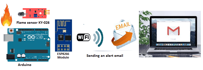
In this project we will realize an intelligent fire detection system with the Arduino board connected to the Internet.
It mainly uses a KY-026 flame sensor.
When the flame sensor detects a flame, the Arduino board sends an alert email by WIFI.
Necessary components
Arduino UNO

The Arduino UNO is a microcontroller board based on the ATmega328P. It has 14 digital input/output pins, 6 analog inputs, a 16 MHz quartz crystal, a USB connection, a power jack, an ICSP header, and a reset button. The Arduino UNO is programmed using the Arduino software (IDE), which is available for Windows, Mac, and Linux. The board can be powered by an external power supply or by USB. It is compatible with a wide range of sensors, actuators, and other devices, which can be connected to it using a variety of communication protocols, such as I2C, SPI, and UART. The Arduino UNO is a popular choice for beginners and hobbyists, as it is easy to use and has a large community of users and developers
KY-026 flame sensor
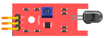
The KY-026 flame sensor is a type of flame sensor that can be used with an Arduino board to detect the presence of a flame. It is a simple and inexpensive sensor that consists of a photodiode, which detects the infrared radiation emitted by a flame, and a comparator circuit, which compares the infrared radiation level to a reference level and outputs a digital signal.
ESP8266 wifi

An ESP8266 WiFi module can be used in combination with an Arduino board to add wireless connectivity to an Arduino project. The ESP8266 is a low-cost Wi-Fi module that can be easily integrated with an Arduino board using the Arduino IDE. It allows the Arduino to connect to a Wi-Fi network and send or receive data over the internet.
To use an ESP8266 module with an Arduino, you will need to connect the ESP8266 to the Arduino’s serial pins (RX, TX) and power pins (VCC, GND). Then, you can use the Arduino IDE to upload a sketch to the Arduino that will configure the ESP8266 to connect to a Wi-Fi network and send or receive data using the Wi-Fi connection.
Connecting wires

When connecting wires to an Arduino or other electronic devices, it’s important to ensure that the wires are connected to the correct pins and in the correct orientation. Typically, the wires are connected to the power, ground, and input/output (I/O) pins on the device. The power and ground pins provide a source of power for the device, while the I/O pins are used to send and receive data.
Test plate
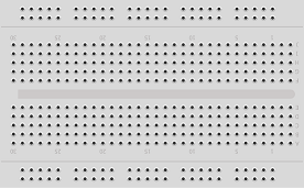
A test plate is used to include the flame sensor module, as well as connectors and other components to interface the sensor with the Arduino. It may also include LEDs, buttons or other input/output devices to test the functionality of the sensor and the microcontroller. The test plate allows for easy testing and validation of the sensor and the Arduino code that is used to interact with it.
Mounting:
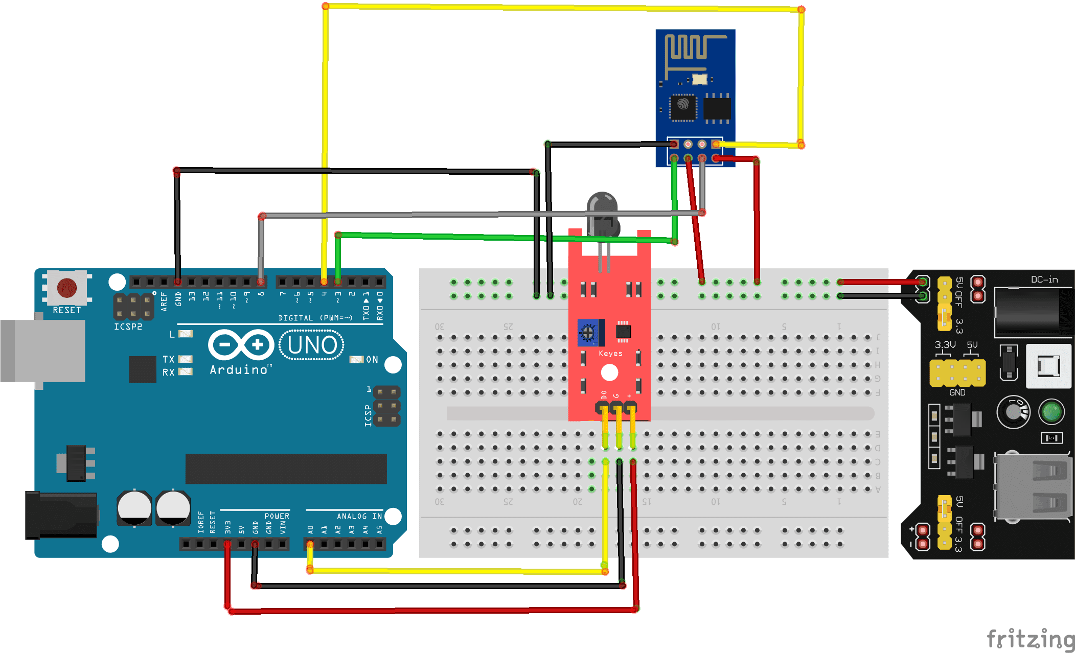
To perform the assembly, you can connect:
KY-026 flame sensor:
-
pin DO to pin A0 of the Arduino board
-
the VCC pin to the 3.3V pin of the Arduino board
-
the GND pin to the GND pin of the Arduino board
For ESP8266 wifi :
-
The RX pin to pin 4 of the Arduino board
-
The TX pin to pin 3 of the Arduino board
-
The GND pin to the GND of the Arduino board
-
The two pins 3V3 and EN to the 5V pin of the power supply module
-
The RST pin to pin 8 of the Arduino board
-
The two pins 3V3 and EN to the 5V pin of the power supply module
Program:
Here is the program of the intelligent fire detection system connected to the Internet:
|
1 2 3 4 5 6 7 8 9 10 11 12 13 14 15 16 17 18 19 20 21 22 23 24 25 26 27 28 29 30 31 32 33 34 35 36 37 38 39 40 41 42 43 44 45 46 47 48 49 50 51 52 53 54 55 56 57 58 59 60 61 62 63 64 65 66 67 68 69 70 71 72 73 74 75 76 77 78 79 80 81 82 83 84 85 86 87 88 89 90 91 92 93 94 95 96 97 98 99 100 101 102 103 104 105 106 107 108 109 110 111 112 113 114 115 116 117 118 119 120 121 122 123 124 125 126 127 128 129 130 131 132 133 134 135 136 137 138 139 140 141 142 143 144 145 146 147 148 149 150 151 152 153 154 155 156 157 158 159 160 161 162 163 164 165 166 167 168 169 170 171 172 173 174 175 176 177 178 179 180 181 182 183 184 185 186 187 188 189 190 191 192 193 194 195 196 197 198 199 200 201 202 203 204 205 206 207 208 209 210 211 212 213 214 215 216 217 218 219 220 221 222 223 224 225 226 227 228 |
#include <Adafruit_ESP8266.h> #include <SoftwareSerial.h> #define ESP_RX 3 #define ESP_TX 4 #define ESP_RST 8 SoftwareSerial softser(ESP_RX, ESP_TX); // Must declare output stream before Adafruit_ESP8266 constructor; can be // a SoftwareSerial stream, or Serial/Serial1/etc. for UART. Adafruit_ESP8266 wifi(&softser, &Serial, ESP_RST); // Must call begin() on the stream(s) before using Adafruit_ESP8266 object. #define ESP_SSID "*************" // Your network name here #define ESP_PASS "*************" // Your network password here char EMAIL_FROM[] = "adresse email de l'émetteur"; char EMAIL_PASSWORD[] = "************"; char EMAIL_TO[] = "adresse email du récepteur"; char SUBJECT[] = "My ESP8266"; char EMAIL_CONTENT[] = "Attention!!! ,\r\n il y a un feu ."; // We'll need your EMAIL_FROM and its EMAIL_PASSWORD base64 encoded, you can use https://www.base64encode.org/ #define EMAIL_FROM_BASE64 "bm9yZXBseUBtZXNhcnRpc2Fucy5mcg==" #define EMAIL_PASSWORD_BASE64 "WVlMdVhKelphVg==" #define HOST "Nom du serveur SMTP" // Find/Google your email provider's SMTP outgoing server name for unencrypted email #define PORT 587 // Find/Google your email provider's SMTP outgoing port for unencrypted email int count = 0; // we'll use this int to keep track of which command we need to send next bool send_flag = false; // we'll use this flag to know when to send the email commands const int btnPin = A0; // le bouton est connecté à la broche A0 de la carte Adruino int btnVal = 0; int analogPin = A0; // KY-026 analog interface int analogVal; //analog readings void setup() { pinMode(btnPin,INPUT_PULLUP); char buffer[50]; // This might work with other firmware versions (no guarantees) // by providing a string to ID the tail end of the boot message: // comment/replace this if you are using something other than v 0.9.2.4! wifi.setBootMarker(F("Version:0.9.2.4]\r\n\r\nready")); softser.begin(9600); // Soft serial connection to ESP8266 Serial.begin(57600); while(!Serial); // UART serial debug Serial.println(F("Adafruit ESP8266 Email")); // Test if module is ready Serial.print(F("Hard reset...")); if(!wifi.hardReset()) { Serial.println(F("no response from module.")); for(;;); } Serial.println(F("OK.")); Serial.print(F("Soft reset...")); if(!wifi.softReset()) { Serial.println(F("no response from module.")); for(;;); } Serial.println(F("OK.")); Serial.print(F("Checking firmware version...")); wifi.println(F("AT+GMR")); if(wifi.readLine(buffer, sizeof(buffer))) { Serial.println(buffer); wifi.find(); // Discard the 'OK' that follows } else { Serial.println(F("error")); } Serial.print(F("Connecting to WiFi...")); if(wifi.connectToAP(F(ESP_SSID), F(ESP_PASS))) { // IP addr check isn't part of library yet, but // we can manually request and place in a string. Serial.print(F("OK\nChecking IP addr...")); wifi.println(F("AT+CIFSR")); if(wifi.readLine(buffer, sizeof(buffer))) { Serial.println(buffer); wifi.find(); // Discard the 'OK' that follows Serial.print(F("Connecting to host...")); Serial.print("Connected.."); wifi.println("AT+CIPMUX=0"); // configure for single connection, //we should only be connected to one SMTP server wifi.find(); wifi.closeTCP(); // close any open TCP connections wifi.find(); Serial.println("Type \"send it\" to send an email"); } else { // IP addr check failed Serial.println(F("error")); } } else { // WiFi connection failed Serial.println(F("FAIL")); } } void loop() { if(!send_flag){ // check if we expect to send an email // Read the analog interface analogVal = analogRead(analogPin); if (analogVal<=11) // If the sensor detects a fire { send_flag = true; // Sending an alert email //Serial.println(btnVal); delay(1000); } } if(send_flag){ // the send_flat is set, this means we are or need to start sending SMTP commands if(do_next()){ // execute the next command count++; // increment the count so that the next command will be executed next time. } } } // do_next executes the SMTP command in the order required. boolean do_next() { switch(count){ case 0: Serial.println("Connecting..."); return wifi.connectTCP(F(HOST), PORT); break; case 1: // send "HELO ip_address" command. Server will reply with "250" and welcome message return wifi.cipSend("HELO computer.com",F("250")); // ideally an ipaddress should go in place // of "computer.com" but I think the email providers // check the IP anyways so I just put anything. break; case 2: // send "AUTH LOGIN" command to the server will reply with "334 username" base 64 encoded return wifi.cipSend("AUTH LOGIN",F("334 VXNlcm5hbWU6")); break; case 3: // send username/email base 64 encoded, the server will reply with "334 password" base 64 encoded return wifi.cipSend(EMAIL_FROM_BASE64,F("334 UGFzc3dvcmQ6")); break; case 4: // send password base 64 encoded, upon successful login the server will reply with 235. return wifi.cipSend(EMAIL_PASSWORD_BASE64,F("235")); break; case 5:{ // send "MAIL FROM:<emali_from@domain.com>" command char mailFrom[50] = "MAIL FROM:<"; // If 50 is not long enough change it, do the same for the array in the other cases strcat(mailFrom,EMAIL_FROM); strcat(mailFrom,">"); return wifi.cipSend(mailFrom,F("250")); break; } case 6:{ // send "RCPT TO:<email_to@domain.com>" command char rcptTo[50] = "RCPT TO:<"; strcat(rcptTo,EMAIL_TO); strcat(rcptTo,">"); return wifi.cipSend(rcptTo,F("250")); break; } case 7: // Send "DATA" command, the server will reply with something like "334 end message with \r\n.\r\n." return wifi.cipSend("DATA",F("354")); break; case 8:{ // apply "FROM: from_name <from_email@domain.com>" header char from[100] = "FROM: "; strcat(from,EMAIL_FROM); strcat(from," "); strcat(from,"<"); strcat(from,EMAIL_FROM); strcat(from,">"); return wifi.cipSend(from); break; } case 9:{ // apply TO header char to[100] = "TO: "; strcat(to,EMAIL_TO); strcat(to,"<"); strcat(to,EMAIL_TO); strcat(to,">"); return wifi.cipSend(to); break; } case 10:{ // apply SUBJECT header char subject[50] = "SUBJECT: "; strcat(subject,SUBJECT); return wifi.cipSend(subject); break; } case 11: return wifi.cipSend("\r\n"); // marks end of header (SUBJECT, FROM, TO, etc); break; case 12: return wifi.cipSend(EMAIL_CONTENT); break; case 13: return wifi.cipSend("\r\n."); // marks end of data command break; case 14: return wifi.cipSend("QUIT"); break; case 15: wifi.closeTCP(); return true; break; case 16: Serial.println("Done"); send_flag = false; count = 0; return false; // we don't want to increment the count break; default: break; } } |

