App Inventor HX711 Micro:bit Project
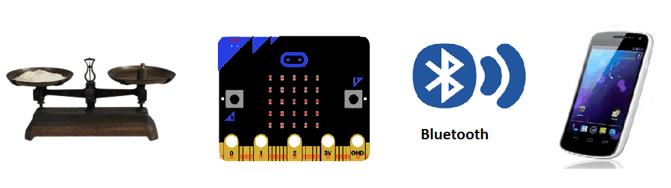
Weighing scale using HX711 and Microbit for remote weight monitoring (by bluetooth)
A weighing scale is a device that is used to measure the weight of an object or a group of objects. There are many different types of weighing scales, including mechanical scales, electronic scales, and digital scales.
Mechanical scales use a spring or balance beam to measure weight. They are typically less accurate than electronic or digital scales, and are often used for rough estimates of weight.
Electronic scales use a load cell to convert weight into an electrical signal. They are typically more accurate than mechanical scales, and can be used to measure weight with greater precision.
Digital scales use a load cell to convert weight into an electrical signal, which is then displayed digitally. They are typically the most accurate type of scale and can display weight in a variety of units.
The HX711 can be used with a Microbit, a small microcontroller board that is designed for educational purposes and is based on the ARM Cortex-M0 processor. The Microbit can be programmed using the Microsoft MakeCode editor or MicroPython, which allows for easy programming and integration with various sensors and actuators.
To interface the HX711 with the Microbit, you can use the I2C protocol, which is supported by both the HX711 and the Microbit. The HX711 has an I2C address that can be configured to one of two options (0x5A or 0x5B) by using the ADDR pin. Once the address is set, you can connect the SDA and SCL pins of the HX711 to the corresponding pins of the Microbit.
The Microbit can then read data from the HX711 using the I2C protocol and can convert the data into weight measurements. The Microbit can also display the weight measurements on its built-in LED matrix, or send the data over Bluetooth to a smartphone or computer for further processing.
Purpose of project:
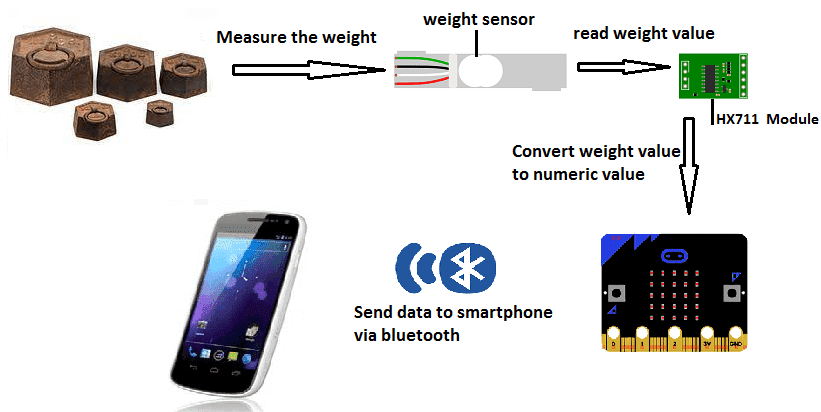
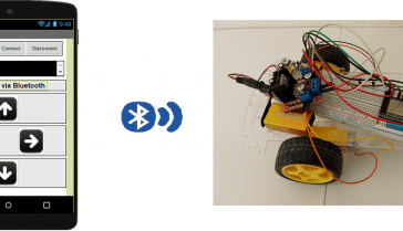
In this project, we will build a weighing scale equipped with the Micro:bit card, the HX711 module and weight sensor for remote weight monitoring by a smartphone via bluetooth.
This is why we will create two programs: a mobile application with App Inventor for the smartphone and a makecode program for the Micro:bit card.
Necessary components
Micro:bit card
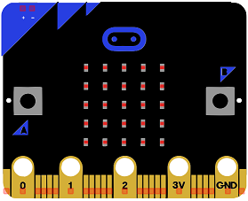
The Micro:bit card, also known as the BBC micro:bit, is a small, programmable microcontroller designed for educational use. It was developed by the BBC in partnership with a number of technology companies in order to promote computer science education in schools. The device is small enough to fit in the palm of a hand and features a range of sensors, inputs, and outputs, including a 5×5 LED matrix display, 2 buttons, an accelerometer, a compass, and Bluetooth connectivity. It can be programmed using a variety of languages, including Microsoft Block Editor, MicroPython, and JavaScript. The device also have features like it can be powered by USB or a battery, and it can be used to control other devices and interact with the physical world.
GPIO expansion board
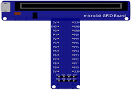
A GPIO expansion board for Microbit is an add-on board that can be used to add additional input/output (I/O) pins to a Microbit microcontroller. These pins can be used to connect a wide variety of sensors, actuators, and other devices to the Microbit, allowing for greater control and flexibility in the system.
GPIO expansion boards for Microbit typically come with a set of headers that connect to the Microbit and provide access to the additional I/O pins. Some expansion boards also come with additional components such as voltage regulators, LEDs, and push buttons that can be used to add more functionality to the system.
In a bottle filling system, a GPIO expansion board for Microbit can be used to connect sensors like infrared sensor, relay to control the operation of a water pump, or a stepper motor driver IC such as UNL2003 to control the movement of the bottle during the filling process. It can also be used to connect other peripherals like LCD screens or other actuators like solenoids or servo motors.
These expansion boards are widely available and can be used to expand the capabilities of a Microbit, making it a versatile and powerful tool for a wide variety of projects, such as a bottle filling system. Some popular expansion boards include the Pimoroni Pico, Adafruit PXT- Microbit, and the Kitronik Inventor’s Kit for Microbit.
hx711 module

The HX711 is an integrated circuit that is commonly used to interface with load cells, which are sensors used to measure weight. The HX711 is a 24-bit analog-to-digital converter (ADC) designed specifically for weigh scales and other industrial control applications. It has two input channels for differential measurements and can convert the analog signals from the load cells into a digital representation of the weight being measured.
The HX711 can be easily interfaced with a microcontroller or a microcontroller board such as Arduino or ESP32 through its digital interface. The HX711 has three pins: VCC, GND, and DT. The VCC and GND pins are used to power the chip and the DT pin is used to send and receive data to and from the microcontroller. The HX711 communicates with the microcontroller using a serial protocol, so it can be easily integrated with any load cell.
The HX711 is a very popular choice for load cell amplifiers because it is inexpensive, easy to use, and has a high resolution and accuracy. It also has a low noise level, making it ideal for use in low-light environments. It’s important to note that the HX711 requires a library to be integrated with the microcontroller and also it’s important to calibrate the load cell before start working with it.
weight sensor
A weight sensor, also known as a load cell, is a device that converts a force, such as weight, into an electrical signal. Load cells are commonly used in industrial and commercial applications to measure the weight of objects, such as in scales and weighing systems.
Load cells typically consist of a metal element, such as a beam or a cylinder, that is designed to deform under an applied force. This deformation causes a change in the resistance of one or more strain gauges, which are small electrical components that are attached to the load cell. These changes in resistance are then converted into an electrical signal that can be read by a microcontroller or other electronic device to determine the weight of an object.
Connecting wires

Wires in a robotic system are used to connect and transmit electrical signals between different components of the robot. These components can include sensors, actuators, motors, and the microcontroller, such as an Arduino. The wires in a robotic system are typically made of copper and are insulated to prevent electrical interference and short circuits.
The type of wires used in a robotic system depends on the specific application and requirements of the robot. For example, a robot that requires high-current power transmission may use thicker, high-gauge wires, while a robot that requires a high degree of flexibility and movement may use thinner, more flexible wires.
Test plate

A test plate is a type of device that is used to test the functionality of other devices or systems. It can be used to test a variety of different components such as sensors, actuators, and electronic circuits. The design and construction of a test plate will depend on the specific components or systems being tested.
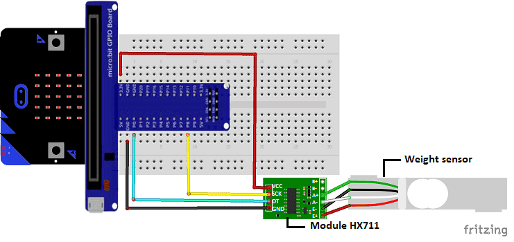
Assembly
-
We connect the VCC pin of the hx711 module to the 3.3V pin of the Micro:bit
-
We connect the GND pin of the hx711 module to the GND pin of the Micro:bit
-
We connect the DT pin of the hx711 module to the P0 pin of the Micro:bit
-
We connect the SCK pin of the hx711 module to the P8 pin of the Micro:bit
-
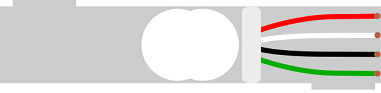
We connect the E+ pin of the hx711 module to the red wire of the weight sensor
-
We connect the E- pin of the hx711 module to the black wire of the weight sensor
-
We connect pin A- of the hx711 module to the white wire of the weight sensor
-
We connect the A+ pin of the hx711 module to the green wire of the weight sensor
Scale operation
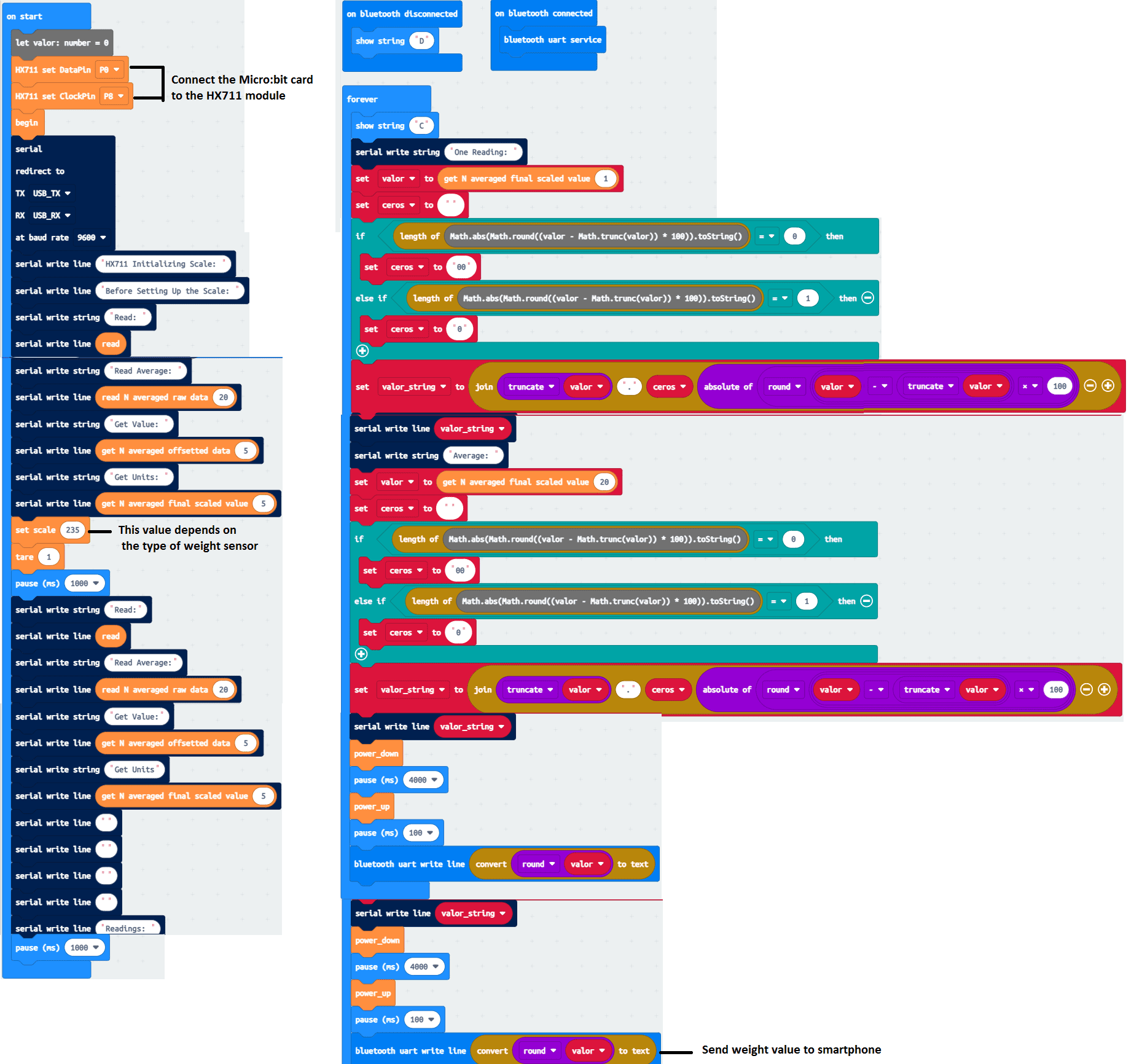
Makecode program
Here is the makecode program that connects the Micro:bit card to the smartphone and sends the measured weight value to the smartphone.
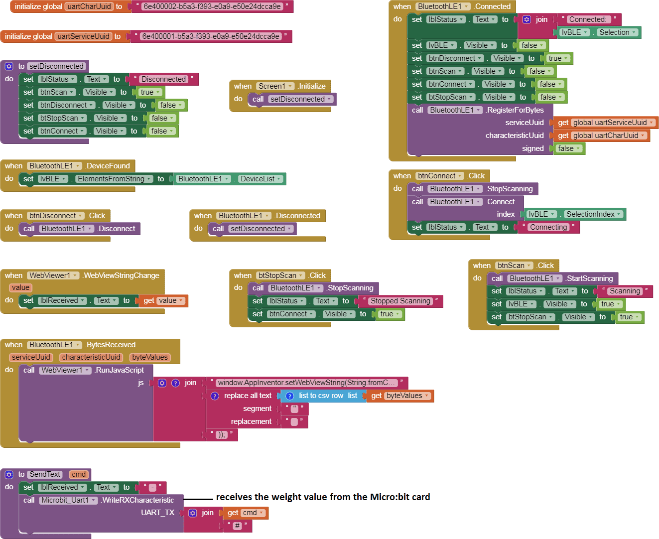
Creating the application with App Inventor:
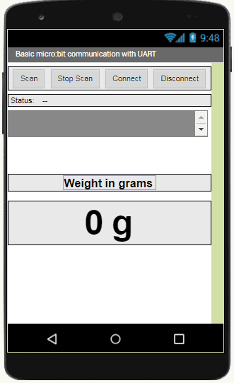
We will create a mobile application named ‘MicrobitPoids’ with App Inventor which allows to receive the weight measured by the Micro:bit card.
We therefore suggest that you create the design of the application, with the following visual:
Programming with App Inventor
To program the application, App Inventor offers us to use the Blocks space which allows you to create a program in the form of a block diagram. Very easy to use but requires some programming logic.
Here is the program of the application made in the Blocks space of the App Inventor:
You can also see

0 commentaire
Leave a comment


Recent tutorials


Most viewed tutorials


Most commented tutorials


Scroll to Top