
La caméra OV7670 peut être utilisée avec une carte Arduino UNO en utilisant une interface appropriée telle qu’un module d’interface ou un adaptateur.
Il existe des modules d’interface spécifiquement conçus pour la caméra OV7670 et les cartes Arduino. Ces modules ont généralement une interface parallèle ou série pour communiquer avec la carte Arduino, ainsi que des broches pour connecter la caméra OV7670. Certains modules peuvent également inclure des composants supplémentaires tels que des régulateurs de tension et des condensateurs pour améliorer la stabilité du système.
Pour utiliser la caméra OV7670 avec la carte Arduino UNO, il est important de comprendre les spécifications de la caméra et les protocoles de communication nécessaires pour la configuration et la capture d’images. Il est également important de noter que la caméra OV7670 nécessite une alimentation de 3,3 V et non de 5 V, comme celle fournie par la carte Arduino. Il est donc important d’utiliser un régulateur de tension approprié ou une alimentation externe pour la caméra.
Il existe des tutoriels et des exemples de code disponibles en ligne pour utiliser la caméra OV7670 avec la carte Arduino UNO. En suivant ces ressources, il est possible de configurer la caméra OV7670 et de capturer des images en temps réel à partir de la carte Arduino UNO.
Comment utiliser la caméra OV7670 avec la carte Arduino UNO ?
Composants nécessaires :
Carte Arduino UNO

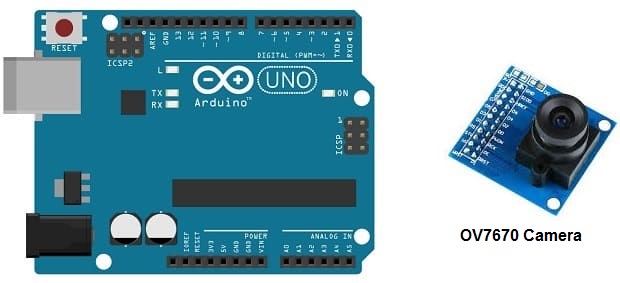
Arduino UNO est une carte de développement open-source basée sur le microcontrôleur ATmega328P d’Atmel. Elle est conçue pour les projets électroniques et les applications de prototypage rapide. La carte Arduino UNO est très populaire dans la communauté des makers et des ingénieurs en raison de sa facilité d’utilisation et de sa grande communauté de soutien.
La carte Arduino UNO dispose de 14 broches d’entrée/sortie numériques (dont 6 peuvent être utilisées comme sorties PWM), 6 entrées analogiques et une horloge de 16 MHz. Elle peut être programmée en utilisant le logiciel Arduino IDE, qui utilise une syntaxe basée sur le langage de programmation C/C++. Elle peut également être programmée en utilisant des langages de haut niveau tels que Scratch.
La carte Arduino UNO est largement utilisée dans une variété de projets électroniques tels que les contrôleurs de robots, les systèmes de surveillance, les instruments de mesure, les dispositifs de contrôle d’éclairage, etc. Sa grande flexibilité, sa facilité d’utilisation et son faible coût en font une solution idéale pour les projets de prototypage et les projets de bricolage.
Carte OV7670
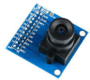
La caméra OV7670 est une caméra CMOS (complémentaire métal-oxyde-semiconducteur) de faible coût et faible consommation d’énergie, conçue pour les applications de capture d’images et de vidéos. Elle est fabriquée par Omnivision Technologies et est largement utilisée dans les projets de développement électronique, les systèmes embarqués, les robots, les drones et les dispositifs de surveillance.
La caméra OV7670 dispose d’un capteur d’image CMOS de 0,3 mégapixel avec une résolution maximale de 640×480 pixels à 30 images par seconde. Elle est capable de capturer des images en couleur RVB (rouge, vert, bleu) et en niveaux de gris avec une sortie de données numériques. Elle dispose également de nombreuses fonctionnalités telles que la réduction du bruit, l’effet miroir, l’auto-exposition, la balance des blancs automatique, etc.
La caméra OV7670 est compatible avec une variété de microcontrôleurs tels que l’Arduino, le Raspberry Pi, le STM32, le PIC, etc. Elle est facile à utiliser et à intégrer dans les projets électroniques. Cependant, elle nécessite une interface appropriée telle qu’un bus de données parallèle ou série pour communiquer avec le microcontrôleur.
2 résistances de 4,7 kΩ

2 résistances de 10 kΩ

Fils de connexion

Les fils de connexion sont des câbles électriques utilisés pour connecter des composants électroniques entre eux ou à une source d’alimentation. Ils sont souvent utilisés dans les projets électroniques pour fournir une connexion électrique fiable entre les différents composants.
plaque d’essai
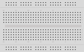
Une plaque d’essai est un support en plastique ou en métal utilisé pour tester des circuits électroniques de manière sécurisée et pratique. Elle est composée de lignes et de colonnes de trous qui permettent de connecter des fils de connexion et des composants électroniques de manière ordonnée.
Module d’alimentation 3.3V/5V
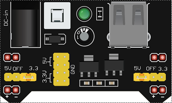
Un module d’alimentation 3,3V/5V est un circuit électronique qui permet de convertir une tension d’entrée donnée en une tension de sortie de 3,3 volts ou de 5 volts, selon le réglage choisi. Ces modules sont couramment utilisés pour fournir une alimentation stable à des composants électroniques tels que des microcontrôleurs, des capteurs, des afficheurs LCD, etc.
Le module d’alimentation 3,3V/5V peut être alimenté par différentes sources telles que des piles, une alimentation USB ou une alimentation externe. Il dispose également souvent d’un régulateur de tension intégré pour assurer une tension de sortie stable et constante, même si la tension d’entrée fluctue.
Montage:
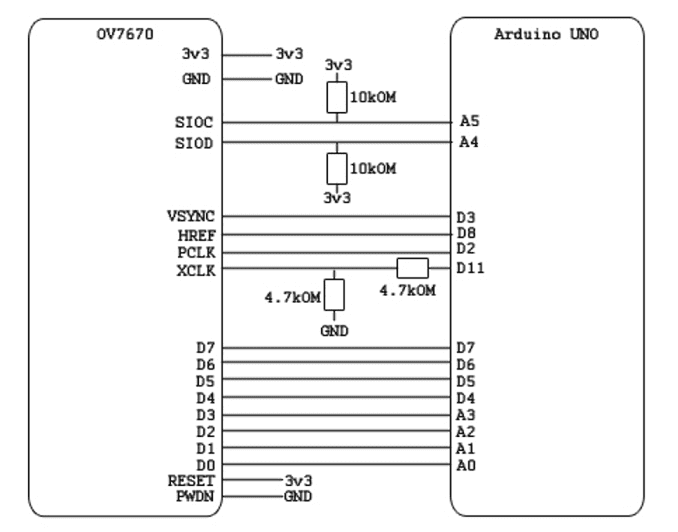
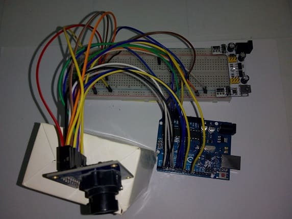
Voici les étapes de base pour connecter la caméra OV7670 à la carte Arduino UNO:
- Alimentation: La caméra OV7670 nécessite une alimentation de 3,3 V, il faut donc connecter la broche d’alimentation 3,3 V du module d’interface à une source d’alimentation externe ou un régulateur de tension qui fournit une tension de 3,3 V.
- Connexion de l’interface: Il est important de connecter l’interface appropriée entre la caméra OV7670 et la carte Arduino UNO. Cela peut être fait en utilisant un module d’interface spécialement conçu pour la caméra OV7670 et les cartes Arduino UNO.
- Connexion des broches: Les broches de la caméra OV7670 doivent être connectées au module d’interface. Les broches incluent les broches d’alimentation, les broches de données et les broches de contrôle. Assurez-vous de connecter les broches correctement en utilisant les schémas de brochage fournis avec le module d’interface.
- Connexion à la carte Arduino UNO: Connectez les broches de données et de contrôle du module d’interface à des broches numériques de la carte Arduino UNO. Les broches numériques utilisées dépendront du module d’interface utilisé et peuvent varier selon les projets. Il est important de vérifier le schéma de brochage du module d’interface pour connaître les broches de connexion.
- Configuration du logiciel: Configurez le logiciel pour communiquer avec la caméra OV7670. Il est possible d’utiliser une bibliothèque pour configurer la caméra OV7670 et capturer des images en temps réel.
Programme Arduino
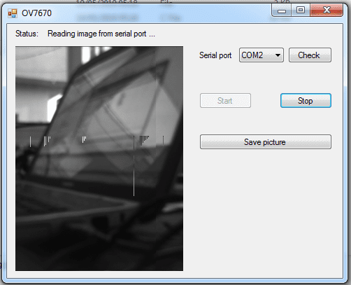
Voici un exemple de programme Arduino de base qui permet de capturer des images en temps réel à partir de la caméra OV7670 et de les afficher sur la fenêtre OV7670.
|
1 2 3 4 5 6 7 8 9 10 11 12 13 14 15 16 17 18 19 20 21 22 23 24 25 26 27 28 29 30 31 32 33 34 35 36 37 38 39 40 41 42 43 44 45 46 47 48 49 50 51 52 53 54 55 56 57 58 59 60 61 62 63 64 65 66 67 68 69 70 71 72 73 74 75 76 77 78 79 80 81 82 83 84 85 86 87 88 89 90 91 92 93 94 95 96 97 98 99 100 101 102 103 104 105 106 107 108 109 110 111 112 113 114 115 116 117 118 119 120 121 122 123 124 125 126 127 128 129 130 131 132 133 134 135 136 137 138 139 140 141 142 143 144 145 146 147 148 149 150 151 152 153 154 155 156 157 158 159 160 161 162 163 164 165 166 167 168 169 170 171 172 173 174 175 176 177 178 179 180 181 182 183 184 185 186 187 188 189 190 191 192 193 194 195 196 197 198 199 200 201 202 203 204 205 206 207 208 209 210 211 212 213 214 215 216 217 218 219 220 221 222 223 224 225 226 227 228 229 230 231 232 233 234 235 236 237 238 239 240 241 242 243 244 245 246 247 248 249 250 251 252 253 254 255 256 257 258 259 260 261 262 263 264 265 266 267 268 269 270 271 272 273 274 275 276 277 278 279 280 281 282 283 284 285 286 287 288 289 290 291 292 293 294 295 296 297 298 299 300 301 302 303 304 305 306 307 308 309 310 311 312 313 314 315 316 317 318 319 320 321 322 323 324 325 326 327 328 329 330 331 332 333 334 335 336 337 338 339 340 341 342 343 344 345 346 347 348 349 350 351 352 353 354 355 356 357 358 359 360 361 362 363 364 365 366 367 368 369 370 371 372 373 374 375 376 377 378 379 380 381 382 383 384 385 386 387 388 389 390 391 392 393 394 395 396 397 398 399 400 401 402 403 404 405 406 407 408 409 410 411 412 413 414 415 416 417 418 419 420 421 422 423 424 425 426 427 428 429 430 431 432 433 434 435 436 437 438 439 440 441 442 443 444 445 446 447 448 449 450 451 452 453 454 455 456 457 458 459 460 461 462 463 464 465 466 467 468 469 470 471 472 473 474 475 476 477 478 479 480 481 482 483 484 485 486 487 488 489 490 491 492 493 494 495 496 497 498 499 500 501 502 503 504 505 506 507 508 509 510 511 512 513 514 515 516 517 518 519 520 521 522 523 524 525 526 527 528 529 530 531 532 533 534 535 536 537 538 539 540 541 542 543 544 545 546 547 548 549 550 551 552 553 554 555 556 557 558 559 560 561 562 563 564 565 566 567 568 569 570 571 572 573 574 575 576 577 578 579 580 581 582 583 584 585 586 587 588 589 590 591 592 593 594 595 596 597 598 599 600 601 602 603 604 605 606 607 608 |
// // Source code for application to transmit image from ov7670 to PC via USB // By Siarhei Charkes in 2015 // http://privateblog.info // #include <stdint.h> #include <avr/io.h> #include <util/twi.h> #include <util/delay.h> #include <avr/pgmspace.h> #define F_CPU 16000000UL #define vga 0 #define qvga 1 #define qqvga 2 #define yuv422 0 #define rgb565 1 #define bayerRGB 2 #define camAddr_WR 0x42 #define camAddr_RD 0x43 /* Registers */ #define REG_GAIN 0x00 /* Gain lower 8 bits (rest in vref) */ #define REG_BLUE 0x01 /* blue gain */ #define REG_RED 0x02 /* red gain */ #define REG_VREF 0x03 /* Pieces of GAIN, VSTART, VSTOP */ #define REG_COM1 0x04 /* Control 1 */ #define COM1_CCIR656 0x40 /* CCIR656 enable */ #define REG_BAVE 0x05 /* U/B Average level */ #define REG_GbAVE 0x06 /* Y/Gb Average level */ #define REG_AECHH 0x07 /* AEC MS 5 bits */ #define REG_RAVE 0x08 /* V/R Average level */ #define REG_COM2 0x09 /* Control 2 */ #define COM2_SSLEEP 0x10 /* Soft sleep mode */ #define REG_PID 0x0a /* Product ID MSB */ #define REG_VER 0x0b /* Product ID LSB */ #define REG_COM3 0x0c /* Control 3 */ #define COM3_SWAP 0x40 /* Byte swap */ #define COM3_SCALEEN 0x08 /* Enable scaling */ #define COM3_DCWEN 0x04 /* Enable downsamp/crop/window */ #define REG_COM4 0x0d /* Control 4 */ #define REG_COM5 0x0e /* All "reserved" */ #define REG_COM6 0x0f /* Control 6 */ #define REG_AECH 0x10 /* More bits of AEC value */ #define REG_CLKRC 0x11 /* Clocl control */ #define CLK_EXT 0x40 /* Use external clock directly */ #define CLK_SCALE 0x3f /* Mask for internal clock scale */ #define REG_COM7 0x12 /* Control 7 */ //REG mean address. #define COM7_RESET 0x80 /* Register reset */ #define COM7_FMT_MASK 0x38 #define COM7_FMT_VGA 0x00 #define COM7_FMT_CIF 0x20 /* CIF format */ #define COM7_FMT_QVGA 0x10 /* QVGA format */ #define COM7_FMT_QCIF 0x08 /* QCIF format */ #define COM7_RGB 0x04 /* bits 0 and 2 - RGB format */ #define COM7_YUV 0x00 /* YUV */ #define COM7_BAYER 0x01 /* Bayer format */ #define COM7_PBAYER 0x05 /* "Processed bayer" */ #define REG_COM8 0x13 /* Control 8 */ #define COM8_FASTAEC 0x80 /* Enable fast AGC/AEC */ #define COM8_AECSTEP 0x40 /* Unlimited AEC step size */ #define COM8_BFILT 0x20 /* Band filter enable */ #define COM8_AGC 0x04 /* Auto gain enable */ #define COM8_AWB 0x02 /* White balance enable */ #define COM8_AEC 0x01 /* Auto exposure enable */ #define REG_COM9 0x14 /* Control 9- gain ceiling */ #define REG_COM10 0x15 /* Control 10 */ #define COM10_HSYNC 0x40 /* HSYNC instead of HREF */ #define COM10_PCLK_HB 0x20 /* Suppress PCLK on horiz blank */ #define COM10_HREF_REV 0x08 /* Reverse HREF */ #define COM10_VS_LEAD 0x04 /* VSYNC on clock leading edge */ #define COM10_VS_NEG 0x02 /* VSYNC negative */ #define COM10_HS_NEG 0x01 /* HSYNC negative */ #define REG_HSTART 0x17 /* Horiz start high bits */ #define REG_HSTOP 0x18 /* Horiz stop high bits */ #define REG_VSTART 0x19 /* Vert start high bits */ #define REG_VSTOP 0x1a /* Vert stop high bits */ #define REG_PSHFT 0x1b /* Pixel delay after HREF */ #define REG_MIDH 0x1c /* Manuf. ID high */ #define REG_MIDL 0x1d /* Manuf. ID low */ #define REG_MVFP 0x1e /* Mirror / vflip */ #define MVFP_MIRROR 0x20 /* Mirror image */ #define MVFP_FLIP 0x10 /* Vertical flip */ #define REG_AEW 0x24 /* AGC upper limit */ #define REG_AEB 0x25 /* AGC lower limit */ #define REG_VPT 0x26 /* AGC/AEC fast mode op region */ #define REG_HSYST 0x30 /* HSYNC rising edge delay */ #define REG_HSYEN 0x31 /* HSYNC falling edge delay */ #define REG_HREF 0x32 /* HREF pieces */ #define REG_TSLB 0x3a /* lots of stuff */ #define TSLB_YLAST 0x04 /* UYVY or VYUY - see com13 */ #define REG_COM11 0x3b /* Control 11 */ #define COM11_NIGHT 0x80 /* NIght mode enable */ #define COM11_NMFR 0x60 /* Two bit NM frame rate */ #define COM11_HZAUTO 0x10 /* Auto detect 50/60 Hz */ #define COM11_50HZ 0x08 /* Manual 50Hz select */ #define COM11_EXP 0x02 #define REG_COM12 0x3c /* Control 12 */ #define COM12_HREF 0x80 /* HREF always */ #define REG_COM13 0x3d /* Control 13 */ #define COM13_GAMMA 0x80 /* Gamma enable */ #define COM13_UVSAT 0x40 /* UV saturation auto adjustment */ #define COM13_UVSWAP 0x01 /* V before U - w/TSLB */ #define REG_COM14 0x3e /* Control 14 */ #define COM14_DCWEN 0x10 /* DCW/PCLK-scale enable */ #define REG_EDGE 0x3f /* Edge enhancement factor */ #define REG_COM15 0x40 /* Control 15 */ #define COM15_R10F0 0x00 /* Data range 10 to F0 */ #define COM15_R01FE 0x80 /* 01 to FE */ #define COM15_R00FF 0xc0 /* 00 to FF */ #define COM15_RGB565 0x10 /* RGB565 output */ #define COM15_RGB555 0x30 /* RGB555 output */ #define REG_COM16 0x41 /* Control 16 */ #define COM16_AWBGAIN 0x08 /* AWB gain enable */ #define REG_COM17 0x42 /* Control 17 */ #define COM17_AECWIN 0xc0 /* AEC window - must match COM4 */ #define COM17_CBAR 0x08 /* DSP Color bar */ /* * This matrix defines how the colors are generated, must be * tweaked to adjust hue and saturation. * * Order: v-red, v-green, v-blue, u-red, u-green, u-blue * They are nine-bit signed quantities, with the sign bit * stored in0x58.Sign for v-red is bit 0, and up from there. */ #define REG_CMATRIX_BASE 0x4f #define CMATRIX_LEN 6 #define REG_CMATRIX_SIGN 0x58 #define REG_BRIGHT 0x55 /* Brightness */ #define REG_CONTRAS 0x56 /* Contrast control */ #define REG_GFIX 0x69 /* Fix gain control */ #define REG_REG76 0x76 /* OV's name */ #define R76_BLKPCOR 0x80 /* Black pixel correction enable */ #define R76_WHTPCOR 0x40 /* White pixel correction enable */ #define REG_RGB444 0x8c /* RGB 444 control */ #define R444_ENABLE 0x02 /* Turn on RGB444, overrides 5x5 */ #define R444_RGBX 0x01 /* Empty nibble at end */ #define REG_HAECC1 0x9f /* Hist AEC/AGC control 1 */ #define REG_HAECC2 0xa0 /* Hist AEC/AGC control 2 */ #define REG_BD50MAX 0xa5 /* 50hz banding step limit */ #define REG_HAECC3 0xa6 /* Hist AEC/AGC control 3 */ #define REG_HAECC4 0xa7 /* Hist AEC/AGC control 4 */ #define REG_HAECC5 0xa8 /* Hist AEC/AGC control 5 */ #define REG_HAECC6 0xa9 /* Hist AEC/AGC control 6 */ #define REG_HAECC7 0xaa /* Hist AEC/AGC control 7 */ #define REG_BD60MAX 0xab /* 60hz banding step limit */ #define REG_GAIN 0x00 /* Gain lower 8 bits (rest in vref) */ #define REG_BLUE 0x01 /* blue gain */ #define REG_RED 0x02 /* red gain */ #define REG_VREF 0x03 /* Pieces of GAIN, VSTART, VSTOP */ #define REG_COM1 0x04 /* Control 1 */ #define COM1_CCIR656 0x40 /* CCIR656 enable */ #define REG_BAVE 0x05 /* U/B Average level */ #define REG_GbAVE 0x06 /* Y/Gb Average level */ #define REG_AECHH 0x07 /* AEC MS 5 bits */ #define REG_RAVE 0x08 /* V/R Average level */ #define REG_COM2 0x09 /* Control 2 */ #define COM2_SSLEEP 0x10 /* Soft sleep mode */ #define REG_PID 0x0a /* Product ID MSB */ #define REG_VER 0x0b /* Product ID LSB */ #define REG_COM3 0x0c /* Control 3 */ #define COM3_SWAP 0x40 /* Byte swap */ #define COM3_SCALEEN 0x08 /* Enable scaling */ #define COM3_DCWEN 0x04 /* Enable downsamp/crop/window */ #define REG_COM4 0x0d /* Control 4 */ #define REG_COM5 0x0e /* All "reserved" */ #define REG_COM6 0x0f /* Control 6 */ #define REG_AECH 0x10 /* More bits of AEC value */ #define REG_CLKRC 0x11 /* Clocl control */ #define CLK_EXT 0x40 /* Use external clock directly */ #define CLK_SCALE 0x3f /* Mask for internal clock scale */ #define REG_COM7 0x12 /* Control 7 */ #define COM7_RESET 0x80 /* Register reset */ #define COM7_FMT_MASK 0x38 #define COM7_FMT_VGA 0x00 #define COM7_FMT_CIF 0x20 /* CIF format */ #define COM7_FMT_QVGA 0x10 /* QVGA format */ #define COM7_FMT_QCIF 0x08 /* QCIF format */ #define COM7_RGB 0x04 /* bits 0 and 2 - RGB format */ #define COM7_YUV 0x00 /* YUV */ #define COM7_BAYER 0x01 /* Bayer format */ #define COM7_PBAYER 0x05 /* "Processed bayer" */ #define REG_COM8 0x13 /* Control 8 */ #define COM8_FASTAEC 0x80 /* Enable fast AGC/AEC */ #define COM8_AECSTEP 0x40 /* Unlimited AEC step size */ #define COM8_BFILT 0x20 /* Band filter enable */ #define COM8_AGC 0x04 /* Auto gain enable */ #define COM8_AWB 0x02 /* White balance enable */ #define COM8_AEC 0x01 /* Auto exposure enable */ #define REG_COM9 0x14 /* Control 9- gain ceiling */ #define REG_COM10 0x15 /* Control 10 */ #define COM10_HSYNC 0x40 /* HSYNC instead of HREF */ #define COM10_PCLK_HB 0x20 /* Suppress PCLK on horiz blank */ #define COM10_HREF_REV 0x08 /* Reverse HREF */ #define COM10_VS_LEAD 0x04 /* VSYNC on clock leading edge */ #define COM10_VS_NEG 0x02 /* VSYNC negative */ #define COM10_HS_NEG 0x01 /* HSYNC negative */ #define REG_HSTART 0x17 /* Horiz start high bits */ #define REG_HSTOP 0x18 /* Horiz stop high bits */ #define REG_VSTART 0x19 /* Vert start high bits */ #define REG_VSTOP 0x1a /* Vert stop high bits */ #define REG_PSHFT 0x1b /* Pixel delay after HREF */ #define REG_MIDH 0x1c /* Manuf. ID high */ #define REG_MIDL 0x1d /* Manuf. ID low */ #define REG_MVFP 0x1e /* Mirror / vflip */ #define MVFP_MIRROR 0x20 /* Mirror image */ #define MVFP_FLIP 0x10 /* Vertical flip */ #define REG_AEW 0x24 /* AGC upper limit */ #define REG_AEB 0x25 /* AGC lower limit */ #define REG_VPT 0x26 /* AGC/AEC fast mode op region */ #define REG_HSYST 0x30 /* HSYNC rising edge delay */ #define REG_HSYEN 0x31 /* HSYNC falling edge delay */ #define REG_HREF 0x32 /* HREF pieces */ #define REG_TSLB 0x3a /* lots of stuff */ #define TSLB_YLAST 0x04 /* UYVY or VYUY - see com13 */ #define REG_COM11 0x3b /* Control 11 */ #define COM11_NIGHT 0x80 /* NIght mode enable */ #define COM11_NMFR 0x60 /* Two bit NM frame rate */ #define COM11_HZAUTO 0x10 /* Auto detect 50/60 Hz */ #define COM11_50HZ 0x08 /* Manual 50Hz select */ #define COM11_EXP 0x02 #define REG_COM12 0x3c /* Control 12 */ #define COM12_HREF 0x80 /* HREF always */ #define REG_COM13 0x3d /* Control 13 */ #define COM13_GAMMA 0x80 /* Gamma enable */ #define COM13_UVSAT 0x40 /* UV saturation auto adjustment */ #define COM13_UVSWAP 0x01 /* V before U - w/TSLB */ #define REG_COM14 0x3e /* Control 14 */ #define COM14_DCWEN 0x10 /* DCW/PCLK-scale enable */ #define REG_EDGE 0x3f /* Edge enhancement factor */ #define REG_COM15 0x40 /* Control 15 */ #define COM15_R10F0 0x00 /* Data range 10 to F0 */ #define COM15_R01FE 0x80 /* 01 to FE */ #define COM15_R00FF 0xc0 /* 00 to FF */ #define COM15_RGB565 0x10 /* RGB565 output */ #define COM15_RGB555 0x30 /* RGB555 output */ #define REG_COM16 0x41 /* Control 16 */ #define COM16_AWBGAIN 0x08 /* AWB gain enable */ #define REG_COM17 0x42 /* Control 17 */ #define COM17_AECWIN 0xc0 /* AEC window - must match COM4 */ #define COM17_CBAR 0x08 /* DSP Color bar */ #define CMATRIX_LEN 6 #define REG_BRIGHT 0x55 /* Brightness */ #define REG_REG76 0x76 /* OV's name */ #define R76_BLKPCOR 0x80 /* Black pixel correction enable */ #define R76_WHTPCOR 0x40 /* White pixel correction enable */ #define REG_RGB444 0x8c /* RGB 444 control */ #define R444_ENABLE 0x02 /* Turn on RGB444, overrides 5x5 */ #define R444_RGBX 0x01 /* Empty nibble at end */ #define REG_HAECC1 0x9f /* Hist AEC/AGC control 1 */ #define REG_HAECC2 0xa0 /* Hist AEC/AGC control 2 */ #define REG_BD50MAX 0xa5 /* 50hz banding step limit */ #define REG_HAECC3 0xa6 /* Hist AEC/AGC control 3 */ #define REG_HAECC4 0xa7 /* Hist AEC/AGC control 4 */ #define REG_HAECC5 0xa8 /* Hist AEC/AGC control 5 */ #define REG_HAECC6 0xa9 /* Hist AEC/AGC control 6 */ #define REG_HAECC7 0xaa /* Hist AEC/AGC control 7 */ #define REG_BD60MAX 0xab /* 60hz banding step limit */ #define MTX1 0x4f /* Matrix Coefficient 1 */ #define MTX2 0x50 /* Matrix Coefficient 2 */ #define MTX3 0x51 /* Matrix Coefficient 3 */ #define MTX4 0x52 /* Matrix Coefficient 4 */ #define MTX5 0x53 /* Matrix Coefficient 5 */ #define MTX6 0x54 /* Matrix Coefficient 6 */ #define REG_CONTRAS 0x56 /* Contrast control */ #define MTXS 0x58 /* Matrix Coefficient Sign */ #define AWBC7 0x59 /* AWB Control 7 */ #define AWBC8 0x5a /* AWB Control 8 */ #define AWBC9 0x5b /* AWB Control 9 */ #define AWBC10 0x5c /* AWB Control 10 */ #define AWBC11 0x5d /* AWB Control 11 */ #define AWBC12 0x5e /* AWB Control 12 */ #define REG_GFI 0x69 /* Fix gain control */ #define GGAIN 0x6a /* G Channel AWB Gain */ #define DBLV 0x6b #define AWBCTR3 0x6c /* AWB Control 3 */ #define AWBCTR2 0x6d /* AWB Control 2 */ #define AWBCTR1 0x6e /* AWB Control 1 */ #define AWBCTR0 0x6f /* AWB Control 0 */ struct regval_list{ uint8_t reg_num; uint16_t value; }; const struct regval_list qvga_ov7670[] PROGMEM = { { REG_COM14, 0x19 }, { 0x72, 0x11 }, { 0x73, 0xf1 }, { REG_HSTART, 0x16 }, { REG_HSTOP, 0x04 }, { REG_HREF, 0xa4 }, { REG_VSTART, 0x02 }, { REG_VSTOP, 0x7a }, { REG_VREF, 0x0a }, /* { REG_HSTART, 0x16 }, { REG_HSTOP, 0x04 }, { REG_HREF, 0x24 }, { REG_VSTART, 0x02 }, { REG_VSTOP, 0x7a }, { REG_VREF, 0x0a },*/ { 0xff, 0xff }, /* END MARKER */ }; const struct regval_list yuv422_ov7670[] PROGMEM = { { REG_COM7, 0x0 }, /* Selects YUV mode */ { REG_RGB444, 0 }, /* No RGB444 please */ { REG_COM1, 0 }, { REG_COM15, COM15_R00FF }, { REG_COM9, 0x6A }, /* 128x gain ceiling; 0x8 is reserved bit */ { 0x4f, 0x80 }, /* "matrix coefficient 1" */ { 0x50, 0x80 }, /* "matrix coefficient 2" */ { 0x51, 0 }, /* vb */ { 0x52, 0x22 }, /* "matrix coefficient 4" */ { 0x53, 0x5e }, /* "matrix coefficient 5" */ { 0x54, 0x80 }, /* "matrix coefficient 6" */ { REG_COM13, COM13_UVSAT }, { 0xff, 0xff }, /* END MARKER */ }; const struct regval_list ov7670_default_regs[] PROGMEM = {//from the linux driver { REG_COM7, COM7_RESET }, { REG_TSLB, 0x04 }, /* OV */ { REG_COM7, 0 }, /* VGA */ /* * Set the hardware window. These values from OV don't entirely * make sense - hstop is less than hstart. But they work... */ { REG_HSTART, 0x13 }, { REG_HSTOP, 0x01 }, { REG_HREF, 0xb6 }, { REG_VSTART, 0x02 }, { REG_VSTOP, 0x7a }, { REG_VREF, 0x0a }, { REG_COM3, 0 }, { REG_COM14, 0 }, /* Mystery scaling numbers */ { 0x70, 0x3a }, { 0x71, 0x35 }, { 0x72, 0x11 }, { 0x73, 0xf0 }, { 0xa2,/* 0x02 changed to 1*/1 }, { REG_COM10, 0x0 }, /* Gamma curve values */ { 0x7a, 0x20 }, { 0x7b, 0x10 }, { 0x7c, 0x1e }, { 0x7d, 0x35 }, { 0x7e, 0x5a }, { 0x7f, 0x69 }, { 0x80, 0x76 }, { 0x81, 0x80 }, { 0x82, 0x88 }, { 0x83, 0x8f }, { 0x84, 0x96 }, { 0x85, 0xa3 }, { 0x86, 0xaf }, { 0x87, 0xc4 }, { 0x88, 0xd7 }, { 0x89, 0xe8 }, /* AGC and AEC parameters. Note we start by disabling those features, then turn them only after tweaking the values. */ { REG_COM8, COM8_FASTAEC | COM8_AECSTEP }, { REG_GAIN, 0 }, { REG_AECH, 0 }, { REG_COM4, 0x40 }, /* magic reserved bit */ { REG_COM9, 0x18 }, /* 4x gain + magic rsvd bit */ { REG_BD50MAX, 0x05 }, { REG_BD60MAX, 0x07 }, { REG_AEW, 0x95 }, { REG_AEB, 0x33 }, { REG_VPT, 0xe3 }, { REG_HAECC1, 0x78 }, { REG_HAECC2, 0x68 }, { 0xa1, 0x03 }, /* magic */ { REG_HAECC3, 0xd8 }, { REG_HAECC4, 0xd8 }, { REG_HAECC5, 0xf0 }, { REG_HAECC6, 0x90 }, { REG_HAECC7, 0x94 }, { REG_COM8, COM8_FASTAEC | COM8_AECSTEP | COM8_AGC | COM8_AEC }, { 0x30, 0 }, { 0x31, 0 },//disable some delays /* Almost all of these are magic "reserved" values. */ { REG_COM5, 0x61 }, { REG_COM6, 0x4b }, { 0x16, 0x02 }, { REG_MVFP, 0x07 }, { 0x21, 0x02 }, { 0x22, 0x91 }, { 0x29, 0x07 }, { 0x33, 0x0b }, { 0x35, 0x0b }, { 0x37, 0x1d }, { 0x38, 0x71 }, { 0x39, 0x2a }, { REG_COM12, 0x78 }, { 0x4d, 0x40 }, { 0x4e, 0x20 }, { REG_GFIX, 0 }, /*{0x6b, 0x4a},*/{ 0x74, 0x10 }, { 0x8d, 0x4f }, { 0x8e, 0 }, { 0x8f, 0 }, { 0x90, 0 }, { 0x91, 0 }, { 0x96, 0 }, { 0x9a, 0 }, { 0xb0, 0x84 }, { 0xb1, 0x0c }, { 0xb2, 0x0e }, { 0xb3, 0x82 }, { 0xb8, 0x0a }, /* More reserved magic, some of which tweaks white balance */ { 0x43, 0x0a }, { 0x44, 0xf0 }, { 0x45, 0x34 }, { 0x46, 0x58 }, { 0x47, 0x28 }, { 0x48, 0x3a }, { 0x59, 0x88 }, { 0x5a, 0x88 }, { 0x5b, 0x44 }, { 0x5c, 0x67 }, { 0x5d, 0x49 }, { 0x5e, 0x0e }, { 0x6c, 0x0a }, { 0x6d, 0x55 }, { 0x6e, 0x11 }, { 0x6f, 0x9e }, /* it was 0x9F "9e for advance AWB" */ { 0x6a, 0x40 }, { REG_BLUE, 0x40 }, { REG_RED, 0x60 }, { REG_COM8, COM8_FASTAEC | COM8_AECSTEP | COM8_AGC | COM8_AEC | COM8_AWB }, /* Matrix coefficients */ { 0x4f, 0x80 }, { 0x50, 0x80 }, { 0x51, 0 }, { 0x52, 0x22 }, { 0x53, 0x5e }, { 0x54, 0x80 }, { 0x58, 0x9e }, { REG_COM16, COM16_AWBGAIN }, { REG_EDGE, 0 }, { 0x75, 0x05 }, { REG_REG76, 0xe1 }, { 0x4c, 0 }, { 0x77, 0x01 }, { REG_COM13, /*0xc3*/0x48 }, { 0x4b, 0x09 }, { 0xc9, 0x60 }, /*{REG_COM16, 0x38},*/ { 0x56, 0x40 }, { 0x34, 0x11 }, { REG_COM11, COM11_EXP | COM11_HZAUTO }, { 0xa4, 0x82/*Was 0x88*/ }, { 0x96, 0 }, { 0x97, 0x30 }, { 0x98, 0x20 }, { 0x99, 0x30 }, { 0x9a, 0x84 }, { 0x9b, 0x29 }, { 0x9c, 0x03 }, { 0x9d, 0x4c }, { 0x9e, 0x3f }, { 0x78, 0x04 }, /* Extra-weird stuff. Some sort of multiplexor register */ { 0x79, 0x01 }, { 0xc8, 0xf0 }, { 0x79, 0x0f }, { 0xc8, 0x00 }, { 0x79, 0x10 }, { 0xc8, 0x7e }, { 0x79, 0x0a }, { 0xc8, 0x80 }, { 0x79, 0x0b }, { 0xc8, 0x01 }, { 0x79, 0x0c }, { 0xc8, 0x0f }, { 0x79, 0x0d }, { 0xc8, 0x20 }, { 0x79, 0x09 }, { 0xc8, 0x80 }, { 0x79, 0x02 }, { 0xc8, 0xc0 }, { 0x79, 0x03 }, { 0xc8, 0x40 }, { 0x79, 0x05 }, { 0xc8, 0x30 }, { 0x79, 0x26 }, { 0xff, 0xff }, /* END MARKER */ }; void error_led(void){ DDRB |= 32;//make sure led is output while (1){//wait for reset PORTB ^= 32;// toggle led _delay_ms(100); } } void twiStart(void){ TWCR = _BV(TWINT) | _BV(TWSTA) | _BV(TWEN);//send start while (!(TWCR & (1 << TWINT)));//wait for start to be transmitted if ((TWSR & 0xF8) != TW_START) error_led(); } void twiWriteByte(uint8_t DATA, uint8_t type){ TWDR = DATA; TWCR = _BV(TWINT) | _BV(TWEN); while (!(TWCR & (1 << TWINT))) {} if ((TWSR & 0xF8) != type) error_led(); } void twiAddr(uint8_t addr, uint8_t typeTWI){ TWDR = addr;//send address TWCR = _BV(TWINT) | _BV(TWEN); /* clear interrupt to start transmission */ while ((TWCR & _BV(TWINT)) == 0); /* wait for transmission */ if ((TWSR & 0xF8) != typeTWI) error_led(); } void wrReg(uint8_t reg, uint8_t dat){ //send start condition twiStart(); twiAddr(camAddr_WR, TW_MT_SLA_ACK); twiWriteByte(reg, TW_MT_DATA_ACK); twiWriteByte(dat, TW_MT_DATA_ACK); TWCR = (1 << TWINT) | (1 << TWEN) | (1 << TWSTO);//send stop _delay_ms(1); } static uint8_t twiRd(uint8_t nack){ if (nack){ TWCR = _BV(TWINT) | _BV(TWEN); while ((TWCR & _BV(TWINT)) == 0); /* wait for transmission */ if ((TWSR & 0xF8) != TW_MR_DATA_NACK) error_led(); return TWDR; } else{ TWCR = _BV(TWINT) | _BV(TWEN) | _BV(TWEA); while ((TWCR & _BV(TWINT)) == 0); /* wait for transmission */ if ((TWSR & 0xF8) != TW_MR_DATA_ACK) error_led(); return TWDR; } } uint8_t rdReg(uint8_t reg){ uint8_t dat; twiStart(); twiAddr(camAddr_WR, TW_MT_SLA_ACK); twiWriteByte(reg, TW_MT_DATA_ACK); TWCR = (1 << TWINT) | (1 << TWEN) | (1 << TWSTO);//send stop _delay_ms(1); twiStart(); twiAddr(camAddr_RD, TW_MR_SLA_ACK); dat = twiRd(1); TWCR = (1 << TWINT) | (1 << TWEN) | (1 << TWSTO);//send stop _delay_ms(1); return dat; } void wrSensorRegs8_8(const struct regval_list reglist[]){ uint8_t reg_addr, reg_val; const struct regval_list *next = reglist; while ((reg_addr != 0xff) | (reg_val != 0xff)){ reg_addr = pgm_read_byte(&next->reg_num); reg_val = pgm_read_byte(&next->value); wrReg(reg_addr, reg_val); next++; } } void setColor(void){ wrSensorRegs8_8(yuv422_ov7670); } void setRes(void){ wrReg(REG_COM3, 4); // REG_COM3 enable scaling wrSensorRegs8_8(qvga_ov7670); } void camInit(void){ wrReg(0x12, 0x80); _delay_ms(100); wrSensorRegs8_8(ov7670_default_regs); wrReg(REG_COM10, 32);//PCLK does not toggle on HBLANK. } void arduinoUnoInut(void) { cli();//disable interrupts /* Setup the 8mhz PWM clock * This will be on pin 11*/ DDRB |= (1 << 3);//pin 11 ASSR &= ~(_BV(EXCLK) | _BV(AS2)); TCCR2A = (1 << COM2A0) | (1 << WGM21) | (1 << WGM20); TCCR2B = (1 << WGM22) | (1 << CS20); OCR2A = 0;//(F_CPU)/(2*(X+1)) DDRC &= ~15;//low d0-d3 camera DDRD &= ~252;//d7-d4 and interrupt pins _delay_ms(3000); //set up twi for 100khz TWSR &= ~3;//disable prescaler for TWI TWBR = 72;//set to 100khz //enable serial UBRR0H = 0; UBRR0L = 1;//0 = 2M baud rate. 1 = 1M baud. 3 = 0.5M. 7 = 250k 207 is 9600 baud rate. UCSR0A |= 2;//double speed aysnc UCSR0B = (1 << RXEN0) | (1 << TXEN0);//Enable receiver and transmitter UCSR0C = 6;//async 1 stop bit 8bit char no parity bits } void StringPgm(const char * str){ do{ while (!(UCSR0A & (1 << UDRE0)));//wait for byte to transmit UDR0 = pgm_read_byte_near(str); while (!(UCSR0A & (1 << UDRE0)));//wait for byte to transmit } while (pgm_read_byte_near(++str)); } static void captureImg(uint16_t wg, uint16_t hg){ uint16_t y, x; StringPgm(PSTR("*RDY*")); while (!(PIND & 8));//wait for high while ((PIND & 8));//wait for low y = hg; while (y--){ x = wg; //while (!(PIND & 256));//wait for high while (x--){ while ((PIND & 4));//wait for low UDR0 = (PINC & 15) | (PIND & 240); while (!(UCSR0A & (1 << UDRE0)));//wait for byte to transmit while (!(PIND & 4));//wait for high while ((PIND & 4));//wait for low while (!(PIND & 4));//wait for high } // while ((PIND & 256));//wait for low } _delay_ms(100); } void setup(){ arduinoUnoInut(); camInit(); setRes(); setColor(); wrReg(0x11, 12); //Earlier it had the value: wrReg(0x11, 12); New version works better for me :) !!!! } void loop(){ captureImg(320, 240); } |

