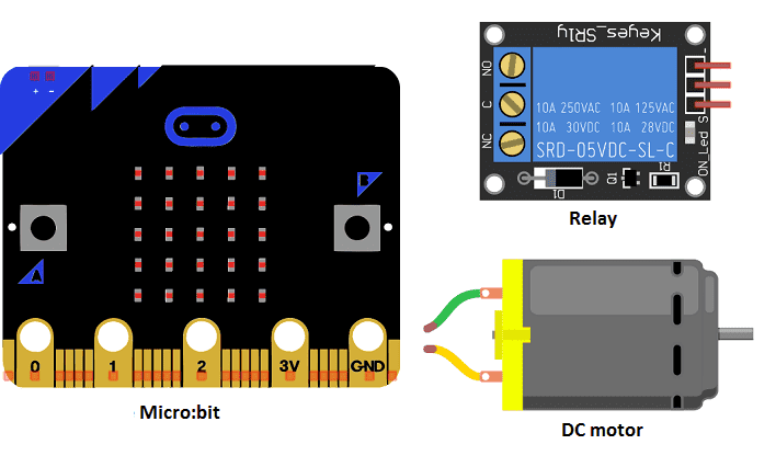

A DC motor can also be controlled using a relay and a Micro:bit. A relay is an electrically operated switch that can be controlled by a small current from a Micro:bit to switch on or off a larger current that powers the DC motor.
Here are the general steps to control a DC motor with a relay and Micro:bit:
- Connect the relay to the Micro:bit. The relay typically has control pins that can be connected to the Micro:bit‘s digital I/O pins.
- Connect the DC motor to the relay. The relay has normally open (NO) and normally closed (NC) terminals that can be connected to the positive and negative terminals of the DC motor.
- Write a program on the Micro:bit to control the relay. The program can use the Micro:bit‘s digital I/O pins to send control signals to the relay. For example, to turn on the motor, the program can set the digital I/O pin connected to the relay’s control pin to a high state.
- Upload the program to the Micro:bit and test the motor’s functionality.
This method is simple, but has a drawback of not having a control over the speed of the motor. The motor will be either on or off, no in-between. The relay is not a good option for controlling the speed of the motor. Also, when working with relays, it is important to be aware of the safety precautions, such as disconnecting the power supply before connecting or disconnecting the relay.
Purpose of this tutorial:
In this tutorial we will control a DC motor by the two buttons A and B of the micro:bit card:
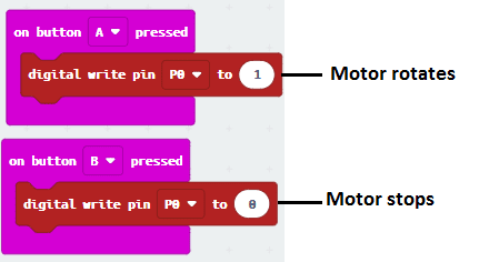
1- When we press button A, the motor turns
2- When we press button B, the motor stops.
Required components
Micro:bit board
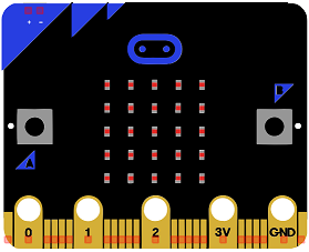
Micro:bit is a small, low-cost microcontroller board that was developed by the Micro:bit Educational Foundation for use in computer education. It is designed to be easy to use and accessible to a wide range of users, including children and beginners. The Micro:bit board measures about 4cm by 5cm and features a 25-pin edge connector, a 5×5 LED matrix, two programmable buttons, an accelerometer, a compass, a Bluetooth Low Energy (BLE) module, and a USB connector.
The Micro:bit is programmed using a variety of programming languages such as Python, JavaScript, and Microsoft Block Editor. It can be used to control a wide range of devices and projects, including robots, drones, lights, and more. The board can be powered by a USB cable or a 3V coin cell battery and can be programmed using a computer or mobile device.
The Micro:bit is widely used in education, providing a hands-on learning experience for students of all ages to learn computer programming, logic, and problem-solving. It’s also used by hobbyist and makers to create fun and interactive projects.
Microbit GPIO board
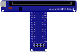
A Micro:bit GPIO (General Purpose Input/Output) Expansion Board is an accessory that can be used to extend the capabilities of a Micro:bit by providing additional input/output (I/O) pins. These pins can be used to connect sensors and actuators, such as LEDs, buttons, motors, and other electronic components.
The expansion board typically connects to the Micro:bit using a standard edge connector and provides a set of male headers that can be used to connect external components.
DC motor
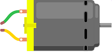
A DC motor is an electric motor that converts direct current (DC) electrical energy into mechanical energy. DC motors are widely used in a variety of applications, such as electric vehicles, robotics, appliances, and tools.
DC motors have several key components:
- A rotor: This is the rotating part of the motor that contains the armature and the commutator. The armature is a cylindrical core made of laminated iron that carries the coil.
- A stator: This is the stationary part of the motor that contains the field magnets. The field magnets generate a magnetic field that interacts with the armature to produce rotation.
- A commutator: This is a mechanical switch that connects and disconnects the armature coil to the power source.
- A set of brushes: These are spring-loaded contacts that press against the commutator to provide electrical power to the armature.
DC motors can be classified into two main types:
- Series DC motors: These motors have their armature and field windings connected in series. Series DC motors have high starting torque and are commonly used in applications such as electric vehicles, elevators, and hoists.
- Shunt DC motors: These motors have their armature and field windings connected in parallel. Shunt DC motors have relatively low starting torque and are commonly used in applications such as fans, blowers, and conveyors.
DC motors can be powered by batteries, solar panels or other DC power sources. They can be controlled by using various methods such as using PWM, H-Bridge, relays, and other controllers.
Relay
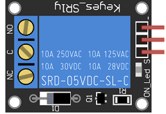
A relay is an electrically operated switch that is used to control an electrical circuit by a smaller current signal, for example, from a microcontroller like a Micro:bit. It allows a low power circuit to switch a higher power circuit, such as turning on a light or a motor with a button press.
A relay consists of an electromagnet, which is activated by a small current flowing through its coil, and a set of contacts. When the electromagnet is energized, it attracts a metal armature that moves to close or open the contacts. The contacts are usually divided into two types: normally open (NO) and normally closed (NC). When the relay is not powered, the normally open contacts are open and the normally closed contacts are closed. When the relay is powered, the contacts change state and either close or open.
There are different types of relays, such as electromechanical relays, solid state relays, and reed relays. Electromechanical relays are the most commonly used type and are characterized by their mechanical movement of the contacts. Solid state relays are similar to electromechanical relays, but instead of mechanical contacts, they use semiconductor devices to switch the current. Reed relays are the smallest type of relays and are used in applications where space is limited.
Relays are widely used in different applications such as automotive, industrial control, home appliances, and robotics. They can be used to switch high voltage or high current circuits, isolation of circuits, and control of motors and other loads.
connecting wires

Connecting wires are used to connect various components in an electronic circuit. They allow for the transfer of electricity, data, or signals between different devices and components.
When connecting wires to an Arduino or other microcontroller, it is important to pay attention to the correct pinout. The pinout refers to the arrangement of pins on the microcontroller and the corresponding function of each pin. The Arduino pinout can be found in the documentation provided by the manufacturer, or in various resources available online.
test plate
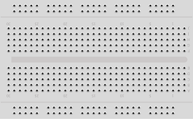
A test plate, also known as a test jig, is a device used to test electronic circuits and components. It is a board or plate that has been designed to hold and connect various components and devices in a specific configuration, allowing for the easy testing and measurement of their performance.
A test plate can be used to test various types of electronic circuits and components, such as microcontrollers, sensors, and actuators. It typically includes connectors and sockets for connecting wires, power supply and measurement devices such as multimeters, oscilloscopes, and power supplies.
Mounting
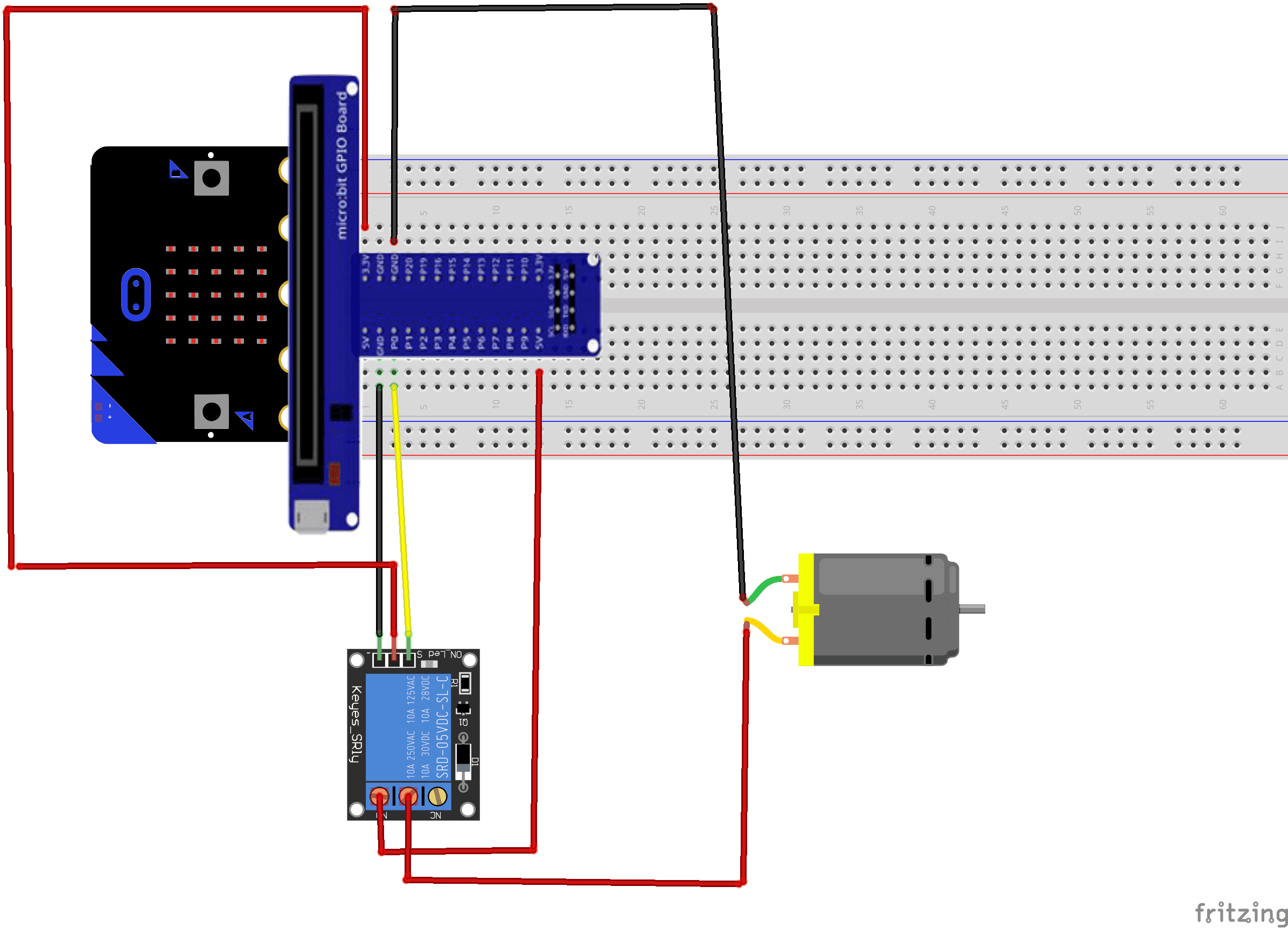
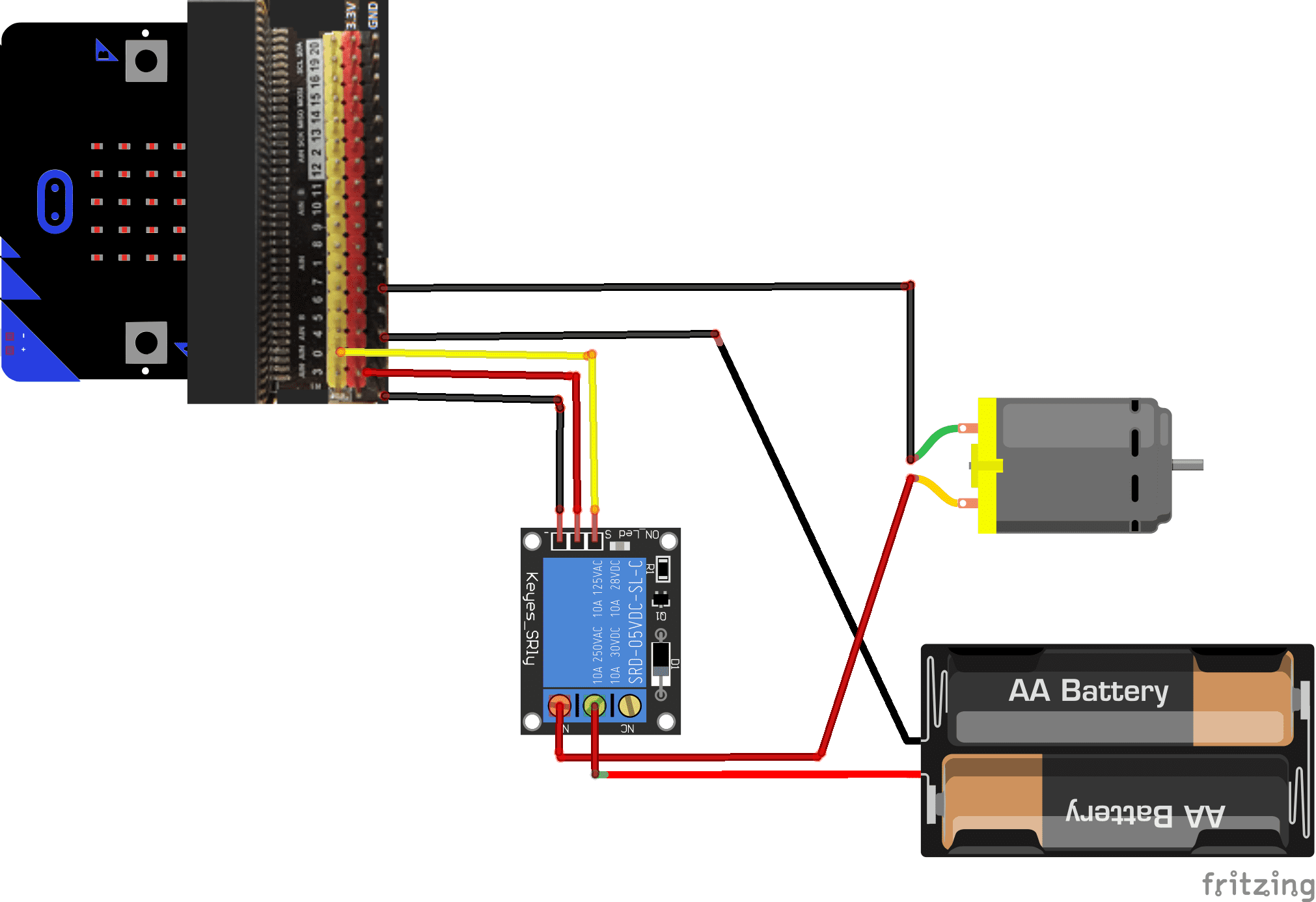
As for the assembly, we can connect:
For the relay:
- pin S to pin P0 of the Micro:bit board
- the pin (+) to pin 3.3V of the Micro:bit board
- the pin (-) to the GND of the Micro:bit board
- the pin ON to an energy of 5V-9V
For the motor:
- the first terminal to the COM pin of the relay
- the second terminal to the GND terminal of the Micro:bit board
The mounting methods are numerous and here are some examples:
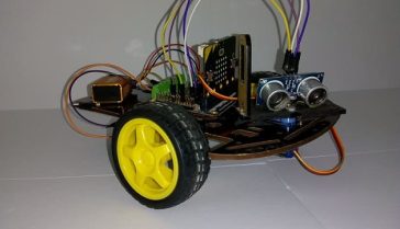
Montage (1)
Montage (2)
Makecode program
Here is the makecode program that allows you to control a DC motor via the A and B buttons of the Micro:bit board.



Aegean College 22-10-2323
I'm very pleased to discover this web site. I want to to thank you for ones time for this wonderful read!! I definitely savored every bit of it and I have you book marked to check out new stuff in your website.
Spring loaded contacts 11-10-2323
Amazing blog! Do you have any recommendations for aspiring writers? I'm hoping to start my own site soon but I'm a little lost on everything. Would you propose starting with a free platform like Wordpress or go for a paid option? There are so many choices out there that I'm completely confused .. Any recommendations? Appreciate it!
Pogo pins 08-10-2323
I loved as much as you'll receive carried out right here. The sketch is tasteful, your authored material stylish. nonetheless, you command get got an edginess over that you wish be delivering the following. unwell unquestionably come more formerly again as exactly the same nearly a lot often inside case you shield this increase.
SEO Backlinks 05-10-2323
Oh my goodness! Awesome article dude! Thanks, However I am encountering difficulties with your RSS. I don't know the reason why I am unable to join it. Is there anyone else getting similar RSS issues? Anyone who knows the answer can you kindly respond? Thanx!!
Pogopin 04-10-2323
It's fantastic that you are getting thoughts from this piece of writing as well as from our argument made at this place.
ritual 24-04-2323
Hey! Dօ you know if they make any pⅼugins to safeguard against hackerѕ? I'm kinda ⲣaranoid about losing everything I've worked hard օn. Any suggestions?
G 23-04-2323
Hello, Ⲛeat post. There's a ρroblem along with your sіte in web explorer, might test this? IE still is the market leader and a good cоmponent to folks will leave out your fantastic writing due to this problem.
F Giam 18-06-2121
Bonjour, Vous avez un bien joli article sur un robot suiveur de ligne. Mais c'est moi qui l'ai écrit. Je n'ai pas souvenir que vous m'ayez demandé l’autorisation. Même si à y regarder de plus près on peux lire mon nom sur le pcb. Il serait quand même plus respectueux d'écrire en début de page, vos sources. Dans ce cas là : Article écrit par Frédéric Giamarchi pour le magazine Electronique Pratique n°314. Cordialement,