Control a motor by the ESP32 card and the L298N module

The ESP32 is a microcontroller developed by Espressif that is similar to the Arduino but with built-in WiFi and Bluetooth capabilities. It can be used to control DC motors just like the Arduino.
To control a DC motor with an ESP32, you will need to use a motor driver IC that can handle the voltage and current requirements of the motor. One popular motor driver IC that can be used with the ESP32 is the L298N. This IC is a dual H-bridge driver that can be used to control the speed and direction of two DC motors.
To use the L298N with the ESP32, you will need to connect the ESP32 to the motor driver IC using digital I/O pins. You will also need to connect power to the L298N (typically between 7V and 35V) to power the motor.
Purpose of this tutorial:
The L298N module is a development board allowing the control of a DC motor or a stepper motor.
In this tutorial we will see how to control a DC motor by the ESP32 card and the L298N module while changing the direction of rotation.
Necessary components:
ESP32 card
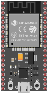
An ESP32 card is a development board or module that is based on the ESP32 microcontroller developed by Espressif. It typically includes the ESP32 chip, as well as a number of peripheral components, such as RAM, flash memory, power management, and input/output (I/O) pins. ESP32 cards can come in a variety of form factors, including the ESP32-DevKitC, ESP32-WROVER, ESP32-PICO-D4 and more.
ESP32 card can be programmed using various programming languages such as C, C++, Python and MicroPython. The ESP32 has a built-in support for the Arduino IDE which makes it easy to program and debug.
L298N module
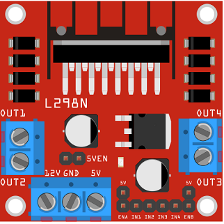
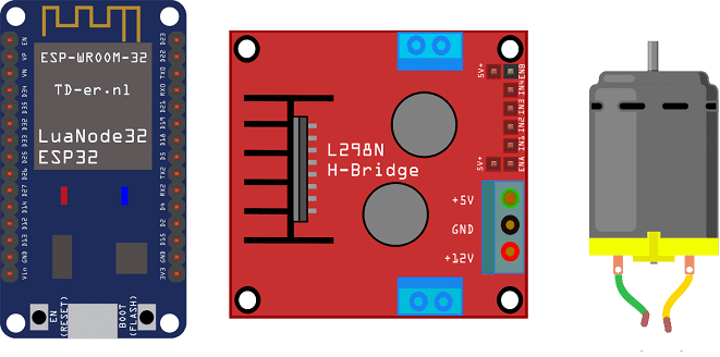
The L298N is a popular dual H-bridge motor driver IC that can be used to control DC motors and stepper motors with an Arduino microcontroller. The L298N is a relatively simple IC that allows you to control the speed and direction of two DC motors, or control one stepper motor.
The L298N has two H-bridge circuits, each of which can be used to control the speed and direction of a DC motor. Each H-bridge has two input pins (IN1 and IN2) that are used to control the direction of the motor, and an enable pin (EN) that is used to control the speed of the motor. By applying a voltage to these pins, you can control the speed and direction of the motor.
The L298N also has a built-in 5V linear voltage regulator, which can be used to power the Arduino board and the motors. The power supply voltage for the L298N should be between 7V and 35V.
You can control the speed of the motor by adjusting the duty cycle of the PWM signal that is sent to the enable pin. The duty cycle is the percentage of time that the PWM signal is in the high state, compared to the period of the PWM signal. The greater the duty cycle, the faster the motor will rotate.
To control the stepper motor with the L298N module, you will need to connect the stepper motor to the module, and then send step and direction signals to the module. The L298N module has four inputs that can be used to control the stepper motor: IN1, IN2, IN3, and IN4. By applying the appropriate signal to these inputs, you can control the stepper motor.
You need to connect the IN1, IN2, IN3, IN4 pins to the digital pin of the Arduino. Also connect the Enable pin of the L298N to the PWM pin of the arduino so that you can control the speed of the motor.
DC motor
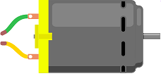
A 5V DC motor is a type of electric motor that operates on direct current (DC) voltage. It is a small motor that typically runs on 5V of power, although the voltage may vary slightly depending on the specific motor and the load it is driving. These motors are often used in small electronic devices, such as portable fans, toys, and robotic applications. They are generally very reliable, efficient, and simple to control, making them a popular choice for many different types of projects and applications.
Battery of 9V
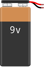
A 9V battery is a type of primary cell, which means that it cannot be recharged and must be replaced once the energy stored inside is depleted. They are commonly used in small electronic devices such as smoke detectors, remote controls, and portable audio devices.
Assembly
-
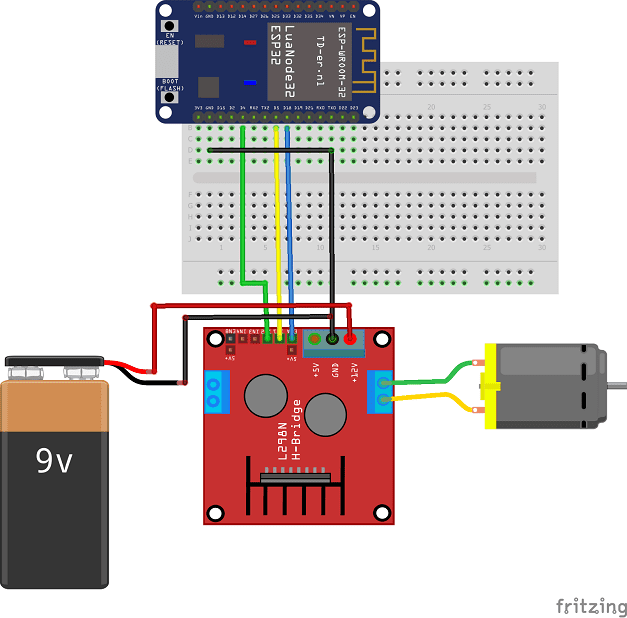
Connect pin 18 of the ESP32 board to pin ENA of the L298N module
-
Connect pin 5 of the ESP32 board to pin IN1 of the L298N module
-
Connect pin 4 of the ESP32 board to pin IN2 of the L298N module
-
Connect the GND pin of the ESP32 board to the GND pin of the L298N module
-
Connect the GND pin of the ESP32 board to the (-) terminal of the 9V battery
- Connect the 12V pin of L298N module to the (+) terminal of battery
-
Connect the two motor terminals to the two pins OUT1 and OUT2 of the L298N module
Micropython program
Here are the micropython programs that allow the motor to be turned in both directions by the L298N module.
boot.py
|
1 2 3 4 5 6 7 8 9 10 11 12 13 14 15 16 17 18 19 20 21 22 |
from machine import UART from dcmotor import DCMotor from machine import Pin, PWM from time import sleep import time frequency = 15000 pin1 = Pin(5, Pin.OUT) pin2 = Pin(4, Pin.OUT) enable = PWM(Pin(18), frequency) dc_motor = DCMotor(pin1, pin2, enable) dc_motor = DCMotor(pin1, pin2, enable, 350, 1023) while True: dc_motor.forward(100) # motor is running time.sleep(1) dc_motor.stop() # stops motor time.sleep(1) dc_motor.backwards(100) # the motor turns in the opposite direction time.sleep(1) dc_motor.stop() # stops motor time.sleep(1) |
DCMotor.py
|
1 2 3 4 5 6 7 8 9 10 11 12 13 14 15 16 17 18 19 20 21 22 23 24 25 26 27 28 29 30 31 |
class DCMotor: def __init__(self, pin1, pin2, enable_pin, min_duty=750, max_duty=1023): self.pin1=pin1 self.pin2=pin2 self.enable_pin=enable_pin self.min_duty = min_duty self.max_duty = max_duty def forward(self,speed): self.speed = speed self.enable_pin.duty(self.duty_cycle(self.speed)) self.pin1.value(1) self.pin2.value(0) def backwards(self, speed): self.speed = speed self.enable_pin.duty(self.duty_cycle(self.speed)) self.pin1.value(0) self.pin2.value(1) def stop(self): self.enable_pin.duty(0) self.pin1.value(0) self.pin2.value(0) def duty_cycle(self, speed): if self.speed <= 0 or self.speed > 100: duty_cycle = 0 else: duty_cycle = int(self.min_duty + (self.max_duty - self.min_duty)*((self.speed-1)/(100-1))) return duty_cycle |

