Control a stepper motor by ESP32

The ESP32 is a microcontroller that can be used to control a stepper motor. It is a powerful, low-cost microcontroller that is well suited for controlling stepper motors and other devices that require precise control over position or speed.
To control a stepper motor using an ESP32, you will need to use a stepper motor driver. The driver acts as an interface between the microcontroller (ESP32) and the stepper motor. It takes the control signals from the ESP32 and converts them into the appropriate signals for the motor to rotate.
You can use the Stepper library that is available for the ESP32 to control the stepper motor. The library provides a simple and easy-to-use interface for controlling stepper motors. To use the library, you will need to include it in your code and create an instance of the Stepper class, passing in the number of steps per revolution for the motor, and the pins that the motor is connected to.
Once you have set up the stepper motor and its driver, you can use the step() function to rotate the motor a specific number of steps in a given direction.
It’s important to note that controlling a stepper motor with an ESP32 requires a bit more setup and wiring compared to a simple DC motor. It also requires a stepper motor driver to convert ESP32‘s control signal to the stepper motor control signal.
Purpose of tutorial:
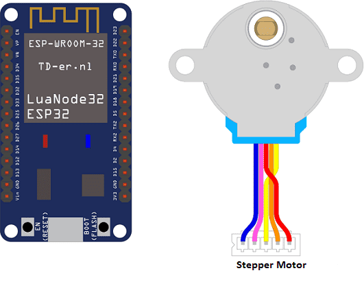
In this tutorial, we will control a stepper motor by the ESP32 card: the stepper motor turns clockwise then it turns counterclockwise.
Necessary components
ESP32 card
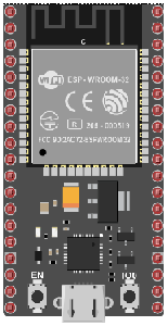
The ESP32 is a microcontroller developed by Espressif Systems, that is based on the popular ESP8266 microcontroller. It is a powerful, low-cost microcontroller that is well suited for a wide range of applications including Internet of Things (IoT) projects, home automation, and wireless communication.
The ESP32 has a dual-core processor, with one core dedicated to handling high-speed connections, and the other core dedicated to handling the user’s application. It also features integrated Wi-Fi and Bluetooth capabilities, making it ideal for wireless communication and IoT projects.
28BYJ-48 stepper motor
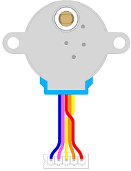
The 28BYJ-48 stepper motor is a small, low-cost stepper motor that is commonly used in small hobby and robotic projects. It is a four-phase, five-wire stepper motor that is driven by a ULN2003 driver IC. The motor has a step angle of 5.625 degrees per step, meaning it takes 64 steps to complete a full rotation. The motor’s maximum torque is 34.3 mNm, so it is not suitable for heavy loads or high-precision applications.
The motor’s step angle is not very precise, but it is still suitable for many small hobby and robotic projects such as small CNC machines, printers, and other projects that require precise and smooth control of the motor.
The 28BYJ-48 stepper motor can be controlled by an ESP32 microcontroller. The ESP32 is a powerful, low-cost microcontroller that is well suited for controlling stepper motors and other devices that require precise control over position or speed.
To control the 28BYJ-48 stepper motor with an ESP32, you will need to connect the motor to a ULN2003 driver IC, and then connect the driver IC to the ESP32. The ULN2003 driver IC has four input pins and four output pins, so you will need to connect the input pins to four digital pins on the ESP32, and connect the output pins to the four wires of the stepper motor.
ULN2003 driver IC
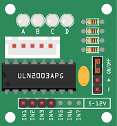
The ULN2003 driver IC is a Darlington transistor array that is commonly used to drive stepper motors and other devices that require high current and/or high voltage. It is a monolithic high-voltage, high-current Darlington transistor array. It consists of seven NPN Darlington pairs that feature high-voltage outputs with common-cathode clamp diode for switching inductive loads.
The ULN2003 driver IC has 16 pins with 4 inputs and 7 outputs. The 4 inputs are connected to the microcontroller, and the 7 outputs are connected to the stepper motor. The inputs of the ULN2003 driver IC are connected to the digital pins of the microcontroller, which is typically an Arduino board, and the outputs are connected to the stepper motor coils. The ULN2003 IC can drive up to 500mA of current per channel.
The ULN2003 driver IC is a simple and convenient way to drive stepper motors and other devices that require high current and/or high voltage. It is relatively easy to use, as it only requires a simple connection to a microcontroller and the device that it is driving.
Battery of 9V
A 9V battery is a type of primary (non-rechargeable) battery that provides a nominal voltage of 9 volts. It is commonly used in portable devices such as smoke detectors, remote controls, and small electronic toys. 9V batteries are also used in some low-power projects such as small robots and simple electronic circuits.
Connecting wires

Wires in a robotic system are used to connect and transmit electrical signals between different components of the robot. These components can include sensors, actuators, motors, and the microcontroller, such as an Arduino. The wires in a robotic system are typically made of copper and are insulated to prevent electrical interference and short circuits.
The type of wires used in a robotic system depends on the specific application and requirements of the robot. For example, a robot that requires high-current power transmission may use thicker, high-gauge wires, while a robot that requires a high degree of flexibility and movement may use thinner, more flexible wires.
Test plate
A test plate for Arduino is a type of test plate that can be used in conjunction with an Arduino microcontroller to automate experiments or tests. The test plate typically contains multiple wells or compartments that can hold samples or test solutions, and is designed to interface with the Arduino’s digital inputs and outputs.
Mounting the ESP32 board with the stepper motor
-
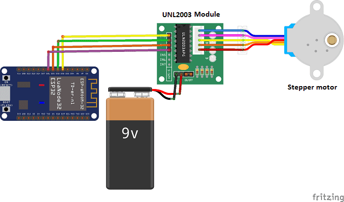
We connect the UNL2003 module to the stepper motor
-
We connect the IN1 pin of the UNL2003 module to the D32 pin of the ESP32 card
-
We connect the IN2 pin of the UNL2003 module to the D33 pin of the ESP32 card
-
We connect the IN3 pin of the UNL2003 module to pin D25 of the ESP32 card
-
We connect the IN4 pin of the UNL2003 module to pin D26 of the ESP32 card
Micropython program
Here are the micropython programs that allow the stepper motor to be controlled by the ESP32 card.
boot.py
|
1 2 3 4 5 6 7 8 9 10 11 12 13 14 15 16 17 18 19 20 21 22 23 |
import Stepper from machine import Pin, ADC import time # for the ESP8266 # In1 = Pin(2,Pin.OUT) # IN1-> GPIO2 # In2 = Pin(0,Pin.OUT) # IN1-> GPIO0 # In3 = Pin(4,Pin.OUT) # IN1-> GPIO4 # In4 = Pin(5,Pin.OUT) # IN1-> GPIO5 # for ESP32 In1 = Pin(32,Pin.OUT) In2 = Pin(33,Pin.OUT) In3 = Pin(25,Pin.OUT) In4 = Pin(26,Pin.OUT) infrarouge = ADC(Pin(34)) s1 = Stepper.create(In1,In2,In3,In4, delay=1) while True: s1.step(500) # rotate the stepper motor clockwise time.sleep(1) s1.step(500,-1) # rotate the stepper motor anti-clockwise time.sleep(1) |
Stepper.py
|
1 2 3 4 5 6 7 8 9 10 11 12 13 14 15 16 17 18 19 20 21 22 23 24 25 26 27 28 29 30 31 32 33 34 35 36 37 38 39 40 41 42 43 44 45 46 47 48 49 50 51 52 53 54 55 56 57 58 59 60 61 62 63 64 65 66 67 68 69 70 71 72 73 74 75 76 77 78 79 80 81 82 83 |
import time # download from: https://github.com/zhcong/ULN2003-for-ESP32 # file: https://github.com/zhcong/ULN2003-for-ESP32/blob/master/Stepper.py # based on: https://github.com/IDWizard/uln2003 # (c) IDWizard 2017, # MIT License. ### usage: ### https://github.com/zhcong/ULN2003-for-ESP32/blob/master/main.py # import Stepper # from machine import Pin # # connected to ESP32, Pin 32,33,25,26 # # using default parameters: delay=2, mode='HALF_STEP' # In1 = Pin(32,Pin.OUT) # In2 = Pin(33,Pin.OUT) # In3 = Pin(25,Pin.OUT) # In4 = Pin(26,Pin.OUT) # s1 = Stepper.create(In1,In2,In3,In4) # # # # one revolution is about 509 steps # s1.step(100) # 100 steps clockwise # s1.step(100,-1) # 100 steps counter clockwise # s1.angle(180) # 180 degree clockwise # s1.angle(360,-1) # 180 degree counter clockwise # only test for uln2003 class Stepper: FULL_ROTATION = int(4075.7728395061727 / 8) # http://www.jangeox.be/2013/10/stepper-motor-28byj-48_25.html HALF_STEP = [ [0, 0, 0, 1], [0, 0, 1, 1], [0, 0, 1, 0], [0, 1, 1, 0], [0, 1, 0, 0], [1, 1, 0, 0], [1, 0, 0, 0], [1, 0, 0, 1], ] FULL_STEP = [ [1, 0, 1, 0], [0, 1, 1, 0], [0, 1, 0, 1], [1, 0, 0, 1] ] def __init__(self, mode, pin1, pin2, pin3, pin4, delay): if mode=='FULL_STEP': self.mode = self.FULL_STEP else: self.mode = self.HALF_STEP self.pin1 = pin1 self.pin2 = pin2 self.pin3 = pin3 self.pin4 = pin4 self.delay = delay # Recommend 10+ for FULL_STEP, 1 is OK for HALF_STEP # Initialize all to 0 self.reset() def step(self, count, direction=1): """Rotate count steps. direction = -1 means backwards""" for x in range(count): for bit in self.mode[::direction]: self.pin1(bit[0]) self.pin2(bit[1]) self.pin3(bit[2]) self.pin4(bit[3]) time.sleep_ms(self.delay) self.reset() def angle(self, r, direction=1): self.step(int(self.FULL_ROTATION * r / 360), direction) def reset(self): # Reset to 0, no holding, these are geared, you can't move them self.pin1(0) self.pin2(0) self.pin3(0) self.pin4(0) def create(pin1, pin2, pin3, pin4, delay=2, mode='HALF_STEP'): return Stepper(mode, pin1, pin2, pin3, pin4, delay) |

