Micro:bit Stepper Motor
Control a stepper motor by Micro:bit
The Micro:bit is a small, low-cost microcontroller board that can be used to control a stepper motor. It is designed for educational purposes and it is easy to use for beginners.
To control a stepper motor using a Micro:bit, you will need to use a stepper motor driver. The driver acts as an interface between the microcontroller (Micro:bit) and the stepper motor. It takes the control signals from the Micro:bit and converts them into the appropriate signals for the motor to rotate.
You can use the Micro:bit‘s built-in JavaScript blocks editor or python to control the stepper motor. The Micro:bit board has several I/O pins that can be used to send signals to the stepper motor driver. The Micro:bit provides a library called « Stepper » which can be used to control the stepper motor.
Purpose of this tutorial:
In this tutorial, we will control a stepper motor by the Microbit card:
-
If button A is pressed, the stepper motor rotates clockwise.
-
If button B is pressed, the stepper motor rotates anti-clockwise.
Necessary components
micro:bit
GPIO expansion board
28BYJ-48 stepper motor
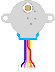
The 28BYJ-48 stepper motor can be controlled by a Micro:bit microcontroller. The Micro:bit is a small, low-cost microcontroller board that is designed for educational purposes and it is easy to use for beginners.
To control the 28BYJ-48 stepper motor with a Micro:bit, you will need to connect the motor to a ULN2003 driver IC, and then connect the driver IC to the Micro:bit. The ULN2003 driver IC has four input pins and four output pins, so you will need to connect the input pins to four digital pins on the Micro:bit, and connect the output pins to the four wires of the stepper motor.
Once the connections are made, you can use the Micro:bit‘s built-in JavaScript blocks editor or python to send control signals to the ULN2003 driver IC, which will in turn control the rotation of the stepper motor. The Micro:bit board provides a library called « Stepper » which can be used to control the stepper motor with the help of the ULN2003 driver IC.
ULN2003 driver IC
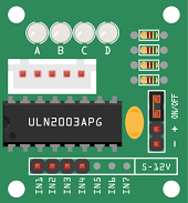
The ULN2003 driver IC is a Darlington transistor array that is commonly used to drive stepper motors and other devices that require high current and/or high voltage. It is a monolithic high-voltage, high-current Darlington transistor array. It consists of seven NPN Darlington pairs that feature high-voltage outputs with common-cathode clamp diode for switching inductive loads.
The ULN2003 driver IC has 16 pins with 4 inputs and 7 outputs. The 4 inputs are connected to the microcontroller, and the 7 outputs are connected to the stepper motor. The inputs of the ULN2003 driver IC are connected to the digital pins of the microcontroller, which is typically an Arduino board, and the outputs are connected to the stepper motor coils. The ULN2003 IC can drive up to 500mA of current per channel.
The ULN2003 driver IC is a simple and convenient way to drive stepper motors and other devices that require high current and/or high voltage. It is relatively easy to use, as it only requires a simple connection to a microcontroller and the device that it is driving.
Battery of 9V
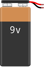
A 9V battery is a type of primary (non-rechargeable) battery that provides a nominal voltage of 9 volts. It is commonly used in portable devices such as smoke detectors, remote controls, and small electronic toys. 9V batteries are also used in some low-power projects such as small robots and simple electronic circuits.
Connecting wires

Wires in a robotic system are used to connect and transmit electrical signals between different components of the robot. These components can include sensors, actuators, motors, and the microcontroller, such as an Arduino. The wires in a robotic system are typically made of copper and are insulated to prevent electrical interference and short circuits.
The type of wires used in a robotic system depends on the specific application and requirements of the robot. For example, a robot that requires high-current power transmission may use thicker, high-gauge wires, while a robot that requires a high degree of flexibility and movement may use thinner, more flexible wires.
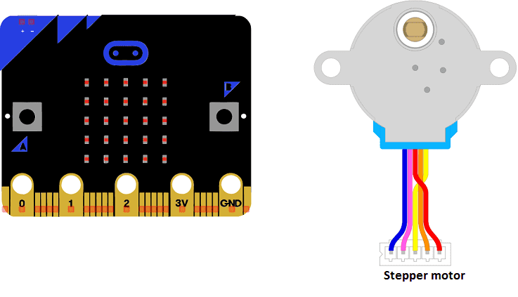
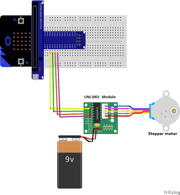
Mounting the Microbit board with the stepper motor
-
We connect the UNL2003 module to the stepper motor
-
We connect the IN1 pin of the UNL2003 module to the P0 pin of the Micro:bit
-
We connect the IN2 pin of the UNL2003 module to the P1 pin of the Micro:bit
-
We connect the IN3 pin of the UNL2003 module to the P2 pin of the Micro:bit
-
We connect the IN4 pin of the UNL2003 module to the P3 pin of the Micro:bit
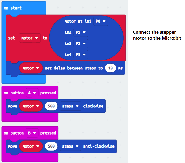
Makecode program
Here is the makecode program which allows to control the stepper motor by the Micro:bit board.
You can also see


0 commentaire
Leave a comment


Recent tutorials


Most viewed tutorials


Most commented tutorials


Scroll to Top