Control the stepper motor by the Arduino

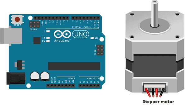
A stepper motor is a type of electric motor that can rotate in precise increments, making it useful for applications that require precise control over position or speed. An Arduino is a microcontroller, which is a type of computer that can be programmed to control various devices, such as sensors and motors. By using an Arduino to control a stepper motor, you can create a system that can precisely position the motor shaft to a specific location or rotate it at a specific speed.
To connect a stepper motor to an Arduino, you will typically need a stepper motor driver, which acts as an interface between the microcontroller and the motor. The driver converts the control signals from the Arduino into the appropriate signals for the motor to rotate. The stepper motor driver also provides power to the motor and allows you to control the speed and direction of the motor.
To control the stepper motor using the Arduino, you will need to write a program (or « sketch » in Arduino terminology) that sends the appropriate signals to the stepper motor driver. The Arduino IDE (Integrated Development Environment) provides a Stepper library that makes it easy to control stepper motors using an Arduino. With this library, you can create an instance of the Stepper class, which provides methods for controlling the stepper motor.
Purpose of tutorial:
In this tutorial, we will control a stepper motor by the Arduino board: the stepper motor turns clockwise then it turns counterclockwise.
Necessary components
Arduino UNO

The Arduino UNO is a microcontroller board based on the ATmega328P. It is a popular choice for beginners and hobbyists as it is easy to use and has a wide range of available libraries and tutorials. The board has 14 digital input/output pins (of which 6 can be used as PWM outputs), 6 analog inputs, a 16 MHz quartz crystal, a USB connection, a power jack, an ICSP header, and a reset button. It can be programmed using the Arduino IDE, which supports C and C++ programming languages and has a simple and user-friendly interface. The board can be powered via USB or an external power source, and can be used to control and interface with various electronic devices and sensors.
US-17H4401 Stepper motor
The US-17H4401 stepper motor is a high-performance, two-phase hybrid stepper motor. It is designed to deliver high torque at low speeds, making it suitable for a wide range of applications that require precise control over position or speed.
The US-17H4401 stepper motor has a step angle of 1.8 degrees per step, and a maximum holding torque of 44 Nm. It has a large rotor inertia, which helps to reduce the effects of resonance, providing smooth and stable operation. It also has a high-precision rotor and stator, which helps to reduce the stepping angle error and improve the accuracy of the motor.
It can be controlled using a stepper motor driver. It is important to note that the US-17H4401 stepper motor requires a high current, so the stepper motor driver should be selected accordingly. To control this motor, you will need to use a stepper motor driver that can handle the voltage and current requirements of the motor.
This motor is widely used in industry, robotics, and other applications that require precise control and high torque.
CNC shield
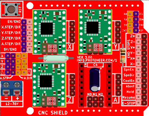
A CNC (Computer Numerical Control) shield is a board that is designed to be used with an Arduino microcontroller to control stepper motors in a CNC machine. It provides a convenient way to connect stepper motors and other devices, such as limit switches and spindle control, to the Arduino.
A CNC shield typically includes several sets of connectors for stepper motor drivers, as well as connectors for other devices, such as limit switches and spindle control. Some CNC shields also include built-in drivers for stepper motors, which can simplify the connection process.
A CNC shield allows you to control the stepper motors with an Arduino board. It uses the Arduino‘s pins to send signals to the stepper motor drivers, which in turn control the stepper motors. By using a CNC shield, you can easily connect stepper motors and other devices to an Arduino and control them using G-code, which is a programming language that is commonly used in CNC machines.
It’s important to note that a CNC shield is not necessary to control a stepper motor with an Arduino, but it can make the process of connecting and controlling stepper motors in a CNC machine much easier and more convenient.
Battery of 9V
A 9V battery is a type of primary (non-rechargeable) battery that provides a nominal voltage of 9 volts. It is commonly used in portable devices such as smoke detectors, remote controls, and small electronic toys. 9V batteries are also used in some low-power projects such as small robots and simple electronic circuits.
Connecting wires

Wires in a robotic system are used to connect and transmit electrical signals between different components of the robot. These components can include sensors, actuators, motors, and the microcontroller, such as an Arduino. The wires in a robotic system are typically made of copper and are insulated to prevent electrical interference and short circuits.
The type of wires used in a robotic system depends on the specific application and requirements of the robot. For example, a robot that requires high-current power transmission may use thicker, high-gauge wires, while a robot that requires a high degree of flexibility and movement may use thinner, more flexible wires.
Assembly of the Arduino board with the stepper motor
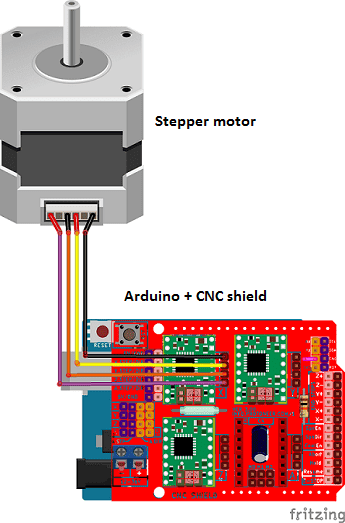
First of all, you have to connect the Arduino board to the CNC board. Then, we connect the stepper motor to the CNC board.
Arduino program
Here is the program which allows to control the stepper motor by the Arduino card.
|
1 2 3 4 5 6 7 8 9 10 11 12 13 14 15 16 17 18 19 20 21 22 23 24 25 26 27 28 |
// pour la configuration du moteur pas à pas const int StepX = 2; const int DirX = 5; int pulseWidthMicros = 1000; // microseconds int millisBtwnSteps = 15000; void setup() { pinMode(StepX,OUTPUT); pinMode(DirX,OUTPUT); } void loop() { translationX(LOW,HIGH,100); //rotate the stepper motor clockwise delay(1000); translationX(HIGH,LOW,100); //rotate the stepper motor anti-clockwise delay(1000); } void translationX (uint8_t pin1, uint8_t pin2,int stepsPerRev1){ digitalWrite(DirX, pin1); // Enables the motor to move in a particular direction // Makes 200 pulses for making one full cycle rotation for (int i = 0; i < stepsPerRev1; i++) { digitalWrite(StepX, pin1); delayMicroseconds(pulseWidthMicros); digitalWrite(StepX, pin2); delayMicroseconds(millisBtwnSteps); } } |

