Controlling a car with smartphone and Arduino

Presentation of robot car
A robot car is a type of mobile robot that is designed to move on wheels or tracks. It can be controlled remotely or autonomously using a microcontroller or computer.
A basic robot car typically consists of the following components:
- Chassis: The chassis is the base of the robot car that holds all the other components. It is typically made of plastic or metal and has wheels or tracks attached to it.
- Microcontroller: The microcontroller is the brain of the robot car. It receives input from sensors and sends commands to the motors to control the movement of the robot car. Common microcontrollers used in robot cars include the Arduino, Raspberry Pi, and ESP32.
- Motors: The motors are used to move the robot car. The most common types of motors used in robot cars are DC motors, stepper motors, and servo motors.
- Sensors: Sensors are used to gather information about the robot’s environment. Common sensors used in robot cars include ultrasonic sensors, infrared sensors, and cameras.
- Battery: The robot car needs a power source to operate. The most common power source is a rechargeable battery.
A robot car can be programmed to move in a specific pattern, follow a line, avoid obstacles, or navigate to a specific location using GPS. It can also be integrated with other devices such as a camera, microphone, or speaker to provide additional functionality.
Controlling a car via Bluetooth involves using a Bluetooth module to establish a wireless connection between a remote device (such as a smartphone or computer) and the car‘s microcontroller. Once the connection is established, the remote device can send commands to the car’s microcontroller, which can then control the car’s movement.
Here are the basic steps to control a car via Bluetooth:
- Connect a Bluetooth module to the car‘s microcontroller. The Bluetooth module should be compatible with the microcontroller and have the appropriate interface to connect to its I/O pins.
- Write the necessary code to establish a connection between the Bluetooth module and the remote device. The code should include the necessary libraries and commands to set up the Bluetooth module as a slave and establish a connection with the remote device.
- Write the code to control the car‘s movement based on the commands received from the remote device. The code should include the necessary libraries and commands to control the car‘s motors, brakes, and other components.
- Connect a remote device (such as a smartphone) to the Bluetooth module. The remote device should have a Bluetooth application that allows the user to send commands to the car‘s microcontroller.
- Once the connection is established, the remote device can send commands to the car‘s microcontroller, which can then control the car‘s movement.
Controlling robot car by Arduino
Controlling a robot car using an Arduino microcontroller involves using the Arduino to receive input from sensors, process the data, and send commands to the robot car‘s motors. The Arduino can be programmed to control the robot car‘s movement based on the input from sensors, or to follow a specific pattern or navigate to a specific location.
Here are the basic steps to control a robot car using an Arduino:
- Connect the Arduino to the robot car‘s motors and sensors. The Arduino should be connected to the motors using motor driver or H-bridge circuits, and connected to the sensors using the appropriate interface (analog or digital).
- Write the necessary code to read the data from the sensors and control the motors. The code should include the necessary libraries and commands to read the sensor data, process the data, and control the motors.
- Upload the code to the Arduino. Once the code is uploaded, the Arduino can start controlling the robot car‘s movement based on the input from the sensors.
- The Arduino can also be connected to other devices such as a Bluetooth module or a GPS module to provide additional functionality, such as remote control or navigation.
Purpose of this tutorial:
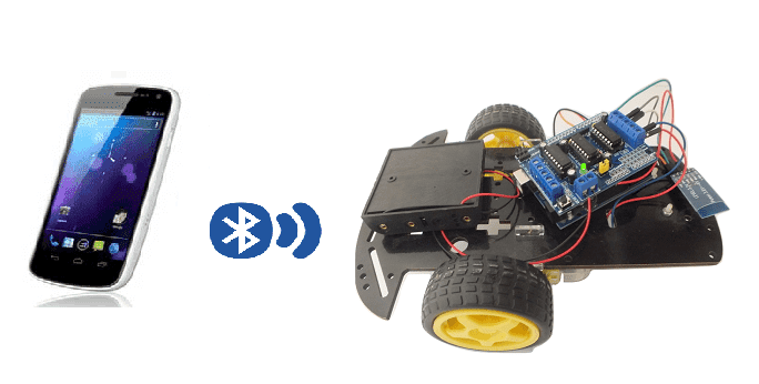
Controlling a robot car using an Arduino microcontroller and a smartphone via Bluetooth involves using a HC-06 Bluetooth module to establish a wireless connection between the smartphone and the Arduino. Once the connection is established, the smartphone can send commands to the Arduino, which can then control the robot car‘s movement.
Here are the basic steps to control a robot car using an Arduino and a smartphone via Bluetooth:
- Connect a HC-06 Bluetooth module to the Arduino. The HC-06 Bluetooth module should be compatible with the Arduino and have the appropriate interface to connect to its I/O pins.
- Write the necessary code to establish a connection between the HC-06 Bluetooth module and the smartphone. The code should include the necessary libraries and commands to set up the Bluetooth module as a slave and establish a connection with the smartphone.
- Write the code to control the robot car‘s movement based on the commands received from the smartphone. The code should include the necessary libraries and commands to control the robot car‘s motors, brakes, and other components.
- Connect a smartphone to the HC-06 Bluetooth module. The smartphone should have a Bluetooth application that allows the user to send commands to the Arduino.
- Once the connection is established, the smartphone can send commands to the Arduino, which can then control the robot car‘s movement.
In this tutorial, we will control a car using the Arduino board and a smartphone.
This is why we are going to create two programs: a mobile application with App Inventor for the smartphone and a program for the Arduino board.
Necessary components
Arduino

The Arduino UNO is a microcontroller board based on the ATmega328P. It has 14 digital input/output pins, 6 analog inputs, a 16 MHz quartz crystal, a USB connection, a power jack, an ICSP header, and a reset button. It is commonly used for DIY electronics projects and for controlling a variety of devices. The board can be programmed with the Arduino IDE (Integrated Development Environment) software, which is a simple programming language based on C/C++.
HC-06 Bluetooth module

The HC-06 Bluetooth module is a small, inexpensive device that allows for wireless communication between electronic devices using the Bluetooth protocol. It can be used to connect microcontrollers such as an Arduino to a smartphone or computer, allowing for wireless control or data transfer.
The HC-06 module operates as a slave device and can be configured to work with a wide range of baud rates. It can be powered by a voltage between 3.3V and 6V and consumes very low power. It supports both AT and transparent transmission mode.
It can be easily interfaced with microcontroller using UART communication. The HC-06 module can be used to implement wireless control and monitoring of various electronic projects, and it can be easily integrated into existing projects to add wireless functionality.
L293D Motor Controller Module
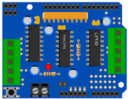
The L293D is a dual H-bridge motor driver integrated circuit (IC) commonly used in robotics and other electronic projects to control the speed and direction of DC motors. It allows for bidirectional control of two DC motors, or one stepper motor, and can drive currents of up to 600mA per channel. The L293D also has built-in protection against voltage spikes and overheating. It requires a supply voltage of between 4.5 and 36V and can be controlled using a variety of microcontrollers such as Arduino or Raspberry Pi.
2 wheel car robot kit
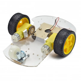
A 2-wheel car robot kit is a collection of components that can be used to build a small, autonomous robot that moves on two wheels. These kits typically include a microcontroller, such as a ESP32 card, to control the robot’s movements, as well as motors, wheels, and other hardware to enable the robot to move and navigate.
2-wheel car robots are often used as educational tools, as they can be used to teach basic principles of robotics, electronics, and programming. They can also be used as a platform for experimenting with different control algorithms, sensors, and other hardware.
This robot kit is composed of:
-
car chassis.
-
2 gear motors (1:48)
-
2 car tires
-
1 universal wheel
test plate
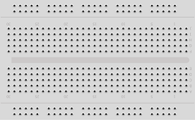
A test plate is a type of device used in robotics to test the functionality and performance of various components or systems. It is typically a physical platform or structure that is designed to hold and support various test items or devices, such as sensors, actuators, motors, or other types of mechanical or electrical components. Test plates can be used to simulate different environments or conditions, such as temperature, humidity, vibration, or other factors, in order to evaluate the performance of the components or systems being tested. They can also be used to perform a variety of diagnostic or diagnostic tests, such as stress testing, endurance testing, or other types of evaluations.
connecting wires

Wires are used to transmit electrical signals and power to various components such as motors, sensors, and microcontrollers. It’s important to properly route and secure the wires to prevent tangles and damage. There are several methods for doing this, including using cable ties, clamps, and wire looms. It’s also a good idea to use different colors or labeling to identify the different wires and their functions. When connecting wires in a robot, it’s important to follow proper safety procedures, such as using the correct wire stripper and connectors, and wearing protective equipment such as gloves and safety glasses.
Mounting
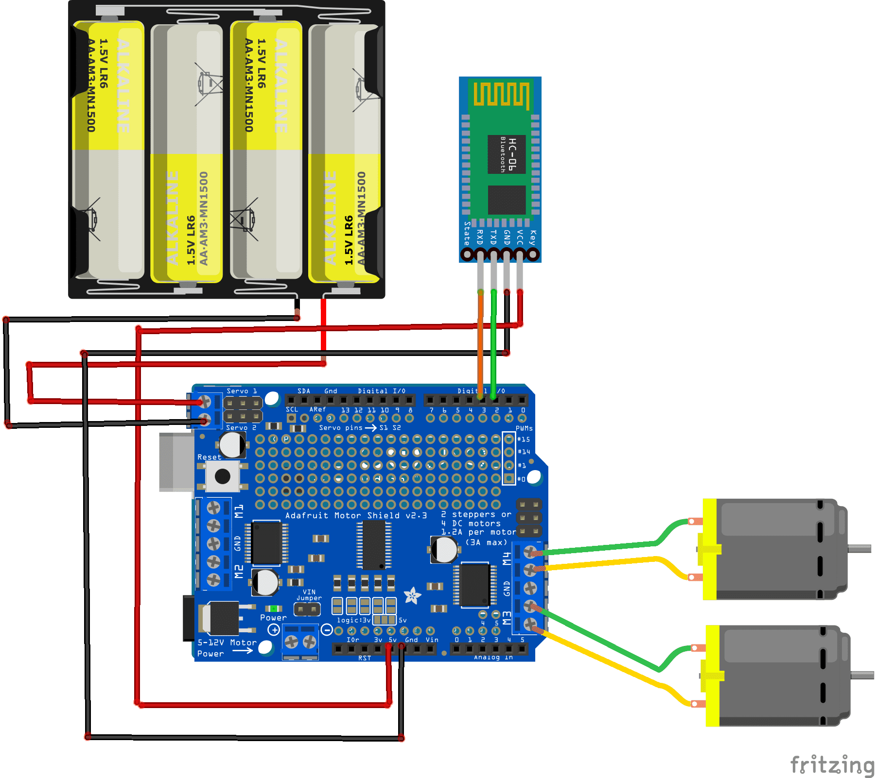
Program
Here is the program which allows to connect the Arduino board to the smartphone and to receive a message containing the command order of the car.
|
1 2 3 4 5 6 7 8 9 10 11 12 13 14 15 16 17 18 19 20 21 22 23 24 25 26 27 28 29 30 31 32 33 34 35 36 37 38 39 40 41 42 43 44 45 46 47 48 |
#include <SoftwareSerial.h> #include <AFMotor.h> AF_DCMotor motor1(3); AF_DCMotor motor2(4); SoftwareSerial hc06(2,3); String cmd=""; void setup(){ motor1.setSpeed(150); motor2.setSpeed(150); //Initialize Serial Monitor Serial.begin(9600); //Initialize Bluetooth Serial Port hc06.begin(9600); } void loop(){ //Read data from HC06 while(hc06.available()>0){ cmd+=(char)hc06.read(); } //Select function with cmd if(cmd!=""){ Serial.print("Command recieved : "); Serial.println(cmd); // We expect ON or OFF from bluetooth if(cmd=="avant"){ motor1.run(FORWARD); //drive the car forward motor2.run(FORWARD); } if(cmd=="arriere"){ motor1.run(BACKWARD);//back up the car motor2.run(BACKWARD); } if(cmd=="gauche"){ motor1.run(FORWARD); //turn the car to the left } if(cmd=="droite"){ motor2.run(FORWARD); //turn the car to the right } if(cmd=="stop"){ motor1.run(RELEASE); // stop car motor2.run(RELEASE); } cmd=""; //reset cmd } delay(100); } |
Creation of the application with App Inventor:
We are going to create a mobile application called ‘commander_voiture_arduino’ with App Inventor which allows the car to be controlled by the smartphone.
We propose to create the design of the application, with the following visual:
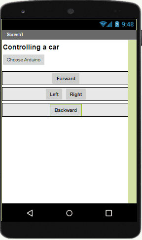
Programming with App Inventor
To program the application, App Inventor offers us to use the Blocks space, which allows you to create a program in the form of a block diagram. Very easy to use but requiring a little programming logic.
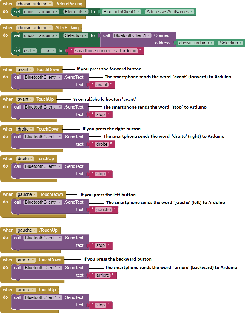
Here is the program of the application created in the Blocks area of the Inventor App:
