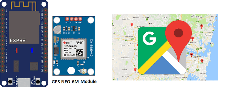
GPS tracking using ESP32 and IoT platform on MQTT

ESP32 and Internet of Things (IoT)
The ESP32 is a microcontroller with built-in WiFi and Bluetooth capabilities that can be programmed using the Python. It is well suited for Internet of Things (IoT) applications because it has the ability to connect to WiFi networks and the internet, allowing it to send and receive data.
One of the main features of the ESP32 that makes it well-suited for IoT applications is its built-in support for WiFi and Bluetooth connectivity. This allows the ESP32 to connect to wireless networks, allowing it to communicate with other devices and access the internet.
The ESP32 also has a wide range of peripheral interfaces such as UART, SPI, I2C, I2S, etc. These interfaces can be used to connect a variety of sensors and actuators to the ESP32, making it a versatile platform for building IoT projects.
The ESP32 also has a built-in real-time clock (RTC), which allows it to keep track of time even when the main power is disconnected. This is useful for IoT applications that need to keep track of time even when disconnected from the internet.
Presentation of GPS tracking
GPS tracking refers to the use of Global Positioning System (GPS) technology to determine the precise location of a device or object. GPS tracking devices, such as GPS trackers, typically use GPS satellites to determine their location and then transmit this information to a central location, such as a computer or smartphone, via a cellular or satellite network.
GPS tracking can be used in a variety of applications, such as:
- Vehicle tracking: GPS tracking devices can be installed in vehicles to monitor their location and movement. This can be used for fleet management, tracking of delivery vehicles, or monitoring the location of company cars.
- Personal tracking: GPS tracking devices can be worn or carried by individuals, allowing their location to be monitored in real-time. This can be used for personal safety, such as for children or elderly persons, or for monitoring the location of employees.
- Asset tracking: GPS tracking devices can be attached to valuable assets, such as equipment or cargo, to monitor their location and movement. This can be used for inventory management, logistics and supply chain management.
To achieve GPS tracking, the device must have a GPS receiver that can process the signals coming from GPS satellites, and a communication module to send this data through a cellular or satellite network to a server where it can be processed and displayed in a user-friendly way.
There are also GPS tracking solutions that work with GPS and other technologies such as WiFi, Bluetooth, and LBS (Location-Based Services) to provide location information.
GPS tracking and ESP32
To achieve GPS tracking using an ESP32, you would need to connect a GPS module to the ESP32 and write code to read and process the GPS data. The ESP32 can communicate with the GPS module using a serial interface such as UART.
The GPS module receives signals from GPS satellites and uses this information to determine its location (latitude, longitude, and altitude) and the current time. The GPS module can then send this information to the ESP32 via the UART interface.
Once the ESP32 receives the GPS data, it can process the data and extract the relevant information, such as the current location and time. The ESP32 can then use this information for various purposes, such as sending the location data to a remote server for tracking, or displaying the location on a local OLED display.
To achieve this, you would need a GPS module that is compatible with the ESP32 and you will have to use a library specifically designed for the ESP32 and GPS module you are using. The library typically provides functions for initializing the GPS module, configuring it, and reading the data.
It’s also important to note that the ESP32 needs to have a clear view of the sky, and it may take some time for the GPS module to get a fix on the satellites’ position. It’s also important to note that the ESP32 needs to be powered on and connected to the GPS module throughout the tracking process.
Presentation of MQTT
MQTT (Message Queuing Telemetry Transport) is a lightweight publish-subscribe messaging protocol that is used for sending data between devices in IoT (Internet of Things) applications. It is designed to be used on low-bandwidth, high-latency networks, making it well-suited for communication between devices in remote locations or with limited resources.
In MQTT, devices are referred to as clients, and they communicate with a central broker. The broker is responsible for receiving messages from clients and forwarding them to the appropriate recipients.
The basic concept in MQTT is the topic, which is a string that identifies a particular message. Clients can subscribe to one or more topics, and they will receive all messages that are published to those topics. Clients can also publish messages to a topic, which will be delivered to all clients that have subscribed to that topic.
MQTT has a small packet size and low overhead, which makes it suitable for use on low-bandwidth, high-latency networks. It also supports Quality of Service (QoS) levels, which allows clients to specify the level of reliability they require for their messages.
MQTT is widely used in IoT applications, such as home automation, industrial control, and remote monitoring. It is supported by a wide range of platforms, including Arduino, Raspberry Pi, and ESP32, and there are many MQTT broker implementations available, such as Mosquitto, HiveMQ, and CloudMQTT.
Objective of this project:
This tutorial shows how to connect NEO-6M GPS module to ESP32 development board, get GPS data and publish latitude and longitude positions to Ubidots IoT cloud in real time via MQTT protocol.

Necessary components
ESP32
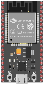
The ESP32 is a low-cost, low-power microcontroller with built-in Wi-Fi and Bluetooth capabilities. It is a popular choice for IoT projects and is commonly used for a variety of applications such as home automation, wireless control, and sensor data logging. The ESP32 features a dual-core processor, a rich set of peripherals, and support for a wide range of protocols. It can be programmed using the Arduino IDE and various other programming languages such as C, C++, and MicroPython.
Additionally, the ESP32 has a wide range of features including:
- A high-performance processor with a clock speed of up to 240 MHz
- Support for various types of wireless connectivity such as Wi-Fi, Bluetooth, and Bluetooth Low Energy (BLE)
- Multiple communication interfaces such as I2C, SPI, UART, and I2S
- A large number of GPIO pins to connect to external devices and sensors
- A built-in security module for secure communication
The ESP32 is often used in projects where a low-cost, low-power device with Wi-Fi and Bluetooth capabilities is needed, and it is commonly used with other sensors and devices to build IoT projects, home automation systems, wireless control systems, and data logging systems.
GPS NEO-6M module

The NEO-6M GPS module is a standalone GPS receiver module that can be used to determine the precise location of a device or object. It uses the Global Positioning System (GPS) to determine its location and can provide information such as latitude, longitude, and altitude.
The NEO-6M module is based on the U-Blox NEO-6M GPS chip and it has a built-in antenna. It is a small, low-power module that can be easily integrated into a wide variety of projects.
The NEO-6M module communicates with the host device via a serial interface, such as UART, I2C or SPI. It sends and receives NMEA data (National Marine Electronics Association) format, which contains information such as the current location, time, speed, and satellite information.
The NEO-6M module has a high sensitivity receiver and it can track up to 22 satellites at a time. It also has a built-in EEPROM, which allows it to store configuration settings and assist in faster satellite acquisition.
The NEO-6M module can be used in a variety of applications, such as vehicle tracking, personal tracking, and asset tracking. It is a low-cost and easy-to-use module, making it a popular choice for hobby projects and DIY projects.
To use the NEO-6M module with an ESP32, you would need to connect the module to the ESP32 according to the wiring diagram provided by the manufacturer and use a library designed for the ESP32 and NEO-6M module to read and process the GPS data.
SSD1306 display
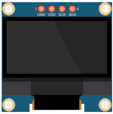
The SSD1306 is a monochrome OLED (Organic Light Emitting Diode) display that can be used to display text and graphics. It is a small, low-power display that can be easily integrated into a wide variety of projects.
The SSD1306 display is controlled using an I2C or SPI interface, which allows it to communicate with a microcontroller or microprocessor. It typically requires only a few connections to the microcontroller, such as Vcc, GND, SDA and SCL for I2C or SCK, MOSI, CS, DC and RST for SPI.
The SSD1306 display has a resolution of 128×64 pixels, and it can display text and graphics using a monochrome pixel format. The display has an integrated charge pump that allows it to operate at a voltage as low as 2.7V. This allows for low power consumption and makes it suitable for battery-powered projects.
The SSD1306 display can be controlled using a variety of libraries that are available for different platforms such as Arduino, Raspberry Pi, ESP32, etc. These libraries provide a set of functions for controlling the display and make it easy to use the SSD1306 display in your projects.
The libraries typically provide functions for initializing the display, clearing the display, setting the cursor position, and writing text or graphics to the display. They also provide functions for controlling the display’s contrast and brightness.
Overall, the SSD1306 display is a versatile and low-power display that can be easily integrated into a wide variety of projects. It is a popular choice for creating small, portable, and battery-powered devices such as digital clocks, temperature displays, and other small graphic displays.
Connecting wires

Connecting wires refers to the process of physically connecting wires or cables to a device or circuit in order to establish an electrical connection. This can be done by using various connectors such as plugs, sockets, or terminal blocks. The wires are typically color-coded to indicate their function, such as red for power, black for ground, and yellow for signals.
Test plate
A test plate is a type of circuit board that is used to test electronic components. It typically consists of a flat board made of a non-conductive material, such as plastic or fiberglass, with a number of holes or pads that are used to connect electronic components. The test plate allows you to connect electronic components and test them easily.
Mounting
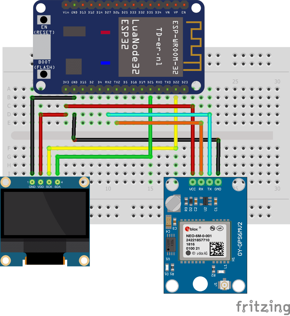
To perform the assembly, you must connect:
For GPS NEO-6M module:
-
the TX pin to the RX pin of the ESP32 board
-
the RX pin to the TX pin of the ESP32 board
-
the GND pin to the GND pin of the ESP32 board
-
the VCC pin to the 3.3V pin of the ESP32 board
For SSD1306 display:
-
the SDA pin to the D21 pin of the ESP32 board
-
the SCL pin to pin D22 of the ESP32 board
-
the GND pin to the GND pin of the ESP32 board
-
the VCC pin to the 3.3V pin of the ESP32 board
Programme en micropython
|
1 2 3 4 5 6 7 8 9 10 11 12 13 14 15 16 17 18 19 20 21 22 23 24 25 26 27 28 29 30 31 32 33 34 35 36 37 38 39 40 41 42 43 44 45 46 47 48 49 50 51 52 53 54 55 56 57 58 59 60 61 62 63 64 65 66 67 68 69 70 71 |
from machine import UART, Pin, SPI,I2C from micropyGPS import MicropyGPS import utime import ssd1306 import network import nmea from umqtt.robust import MQTTClient ubidotsToken = "***********************" clientID = "RANDOM-ALPHA-NUMERIC-NAME_OR_IMEI DEVICE ID" client = MQTTClient("clientID", "industrial.api.ubidots.com", 1883, user = ubidotsToken, password = ubidotsToken) WiFi_SSID = "************" WiFi_PASS = "************" def do_connect(): wlan = network.WLAN(network.STA_IF) wlan.active(True) if not wlan.isconnected(): print('connecting to network...') wlan.connect(WiFi_SSID, WiFi_PASS) while not wlan.isconnected(): pass print('network config:', wlan.ifconfig()) do_connect() i2c = I2C(-1, scl=Pin(22), sda=Pin(21)) oled_width = 128 oled_height = 64 oled = ssd1306.SSD1306_I2C(oled_width, oled_height, i2c) oled.text('Carte', 0, 0) # Afficher les deux mots '' oled.text('ESP32', 0, 10) oled.show() uart = UART(2, 9600) now = utime.ticks_ms() sentence = '' state = '' my_nmea = nmea.nmea(debug=1) while 1: while uart.any(): b = uart.read() my_nmea.parse(b) if utime.ticks_diff(utime.ticks_ms(), now) > 5000: now = utime.ticks_ms() print('{} {}'.format( my_nmea.latitude, my_nmea.longitude)) client.connect() lat = my_nmea.latitude lng = my_nmea.longitude var = 1.5 msg = b'{"location": {"value":%s, "context":{"lat":%s, "lng":%s}}}' % (var, lat, lng) print(msg) client.publish(b"/v1.6/devices/ESP32", msg)#envoi de la position du GPS vers le cloud Ubidots IoT oled.fill(0) y = 0 dy = 10 oled.text("Lat:{}".format(my_nmea.latitude), 0, y) y += dy oled.text("Lon:{}".format(my_nmea.longitude), 0, y) oled.show() |
Remarque: il faut importer ces bibliothèque suivantes: ssd1306, simple, nmea et micropyGPS



Bernd 24-03-2323
Hi, it might be a little late but I'll post my findings nevertheless :-) I've needed to modify the following: - add missing client.disconnect() after oled.show() - add keepalive 30 in client = MQTTClient(clientID, , keepalive=30) - add missing dprint(self,a,b) as the dprint lib was missing (need to figure out how to add the lib) Thanks for posting such a great example! Cheers Bernd
Lakesha 14-07-2222
Hey! I know this is somewhat off topic but I was wondering if you knew where I could find a captcha plugin for my comment form? I'm using the same blog platform as yours and I'm having difficulty finding one? Thanks a lot! Feel free to surf to my webpage houston junk car buyer
Hans 26-05-2222
I have read so many posts concerning the blogger lovers but this article is actually a nice post, keep it up.