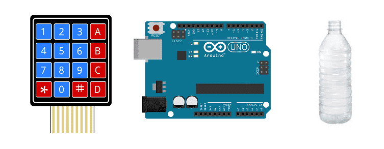

A water filling system is a type of system that is used to automatically fill water containers, such as tanks, reservoirs, or bottles. This system can be used in various applications such as industrial, agricultural, and domestic use. The system can be designed to be operated manually or automatically.
An automatic water filling system typically includes a water source, a pump, a control system, and a filling mechanism. The water source can be a well, a municipal water supply, or a water storage tank. The pump is used to draw water from the source and deliver it to the filling mechanism. The control system is used to regulate the flow of water and to start and stop the filling process. The filling mechanism can be a simple valve or a more complex system that includes sensors and a control system to ensure accurate and precise filling.
The water filling system can be designed to fill containers of various sizes and shapes. The system can also include additional features such as water filtration, water treatment, and monitoring systems to ensure the quality of the water being filled.
It is important to design the system based on the specific requirements of the application and to ensure that it meets local and national codes and regulations. Proper maintenance and regular inspections are also necessary to ensure the system is functioning properly and to prevent water contamination or other hazards.
A water filling system controlled by Arduino is a type of automatic water filling system that uses an Arduino microcontroller to control the various components of the system. The Arduino can be used to control a pump, valves, and sensors to regulate the flow of water and to start and stop the filling process.
The system typically includes a water source, a pump, an Arduino microcontroller, and a filling mechanism. The water source can be a well, a municipal water supply, or a water storage tank. The pump is used to draw water from the source and deliver it to the filling mechanism. The Arduino microcontroller is used to control the pump, valves, and sensors, as well as to monitor the system and provide feedback to the user. The filling mechanism can be a simple valve or a more complex system that includes sensors and a control system to ensure accurate and precise filling.
The Arduino can be programmed using the Arduino IDE, which supports C and C++ programming languages and has a simple and user-friendly interface. There are also several libraries available for the Arduino that can be used to control the pump and valves, as well as to read sensor data and provide feedback to the user.
Purpose of project:
In this project, we will design and build a prototype automatic bottle filling machine using the Arduino board:
The Arduino board performs all control functions.
The desired amount of liquid to be filled is first given by the user via the 4×4 matrix keypad and the input value is displayed on the 16×2 LCD screen. The amount of liquid entered must be between ( 0 and 1500ml).
Water is drawn from the tank by the water pump and passes through the liquid flow sensor which allows the water flow value to be sent to the Arduino board.
Finally, the relay cuts off the connection of the water pump when the liquid that has passed through the yf-s401 sensor is almost equal to the amount given by the user.
Operation of the filling system:

Necessary components
Arduino UNO

The Arduino UNO is a microcontroller board based on the ATmega328P. It is a popular choice for beginners and hobbyists as it is easy to use and has a wide range of available libraries and tutorials. The board has 14 digital input/output pins (of which 6 can be used as PWM outputs), 6 analog inputs, a 16 MHz quartz crystal, a USB connection, a power jack, an ICSP header, and a reset button. It can be programmed using the Arduino IDE, which supports C and C++ programming languages and has a simple and user-friendly interface. The board can be powered via USB or an external power source, and can be used to control and interface with various electronic devices and sensors.
yf-s401 sensor

The YF-S401 sensor is a type of water flow sensor that can be used to measure the flow rate and volume of fluid flowing through a pipe. It can be used in various applications such as irrigation systems, water treatment plants, and industrial process control. The YF-S401 sensor is typically used in conjunction with an Arduino microcontroller to read and process the sensor data.
To use the YF-S401 sensor with an Arduino, you will need to connect the sensor to the Arduino’s digital input pins. The sensor has three pins: GND, VCC, and Signal. GND should be connected to GND of the Arduino, VCC to 5V, and Signal to a digital pin. Once the connections are made, you can use the Arduino to read the sensor’s output signal and calculate the flow rate and volume of fluid flowing through the pipe.
The YF-S401 sensor generates a frequency signal, which is proportional to the flow rate. So, you can use the Arduino’s pulseIn function to measure the frequency of the signal, and then use that frequency to calculate the flow rate. There are libraries available that can simplify the process of reading and processing the sensor data, such as the FlowMeter library.
It is important to follow the sensor’s datasheet and the manufacturer’s instructions when using the YF-S401 sensor with an Arduino, and also to keep in mind that some devices may require some calibration, and you will need to take into account the sensor’s maximum and minimum flow rate, as well as the pipe size, to get accurate measurements.
12V water pump
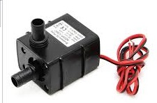
A water pump that operates at 12V is a type of pump that is designed to run on a 12-volt DC power supply. These types of pumps are commonly used in automotive, marine, and RV applications, as well as in small scale irrigation, water treatment and other similar systems.
One of the advantages of using a 12V water pump is that it can be powered by a car battery or a deep-cycle battery, which makes it portable and convenient for use in remote locations. Additionally, these pumps are relatively low power and energy efficient, which makes them ideal for use in solar-powered systems.
The use of a 12V water pump with an Arduino microcontroller requires an external power source, as the Arduino can’t provide the needed power to operate the pump. A relay can be used to switch the pump on and off using the Arduino digital pins, and also a voltage regulator can be used to step down the voltage from the external power source to 12V.
To use a water pump with an Arduino, you will need to connect the pump to the Arduino‘s digital output pins. The pump typically has two wires, one for power and one for ground. These wires can be connected to the Arduino‘s 12V and GND pins, respectively. Once the connections are made, you can use the Arduino’s digital output pins to control the pump.
relay
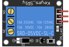
A relay is an electronic switch that can be controlled by an Arduino microcontroller to turn a water pump on and off. When the relay is energized, it closes an electrical circuit, allowing electricity to flow through the pump and turn it on. When the relay is de-energized, it opens the circuit, cutting off the electricity and turning the pump off.
To use a relay to control a water pump with an Arduino, you will need to connect the relay to the Arduino‘s digital output pins. The relay typically has three pins, VCC, GND, and IN. VCC should be connected to 5V of the Arduino, GND to GND, and IN to a digital pin of the Arduino. Once the connections are made, you can use the Arduino‘s digitalWrite function to turn the relay on and off, and thus control the water pump.
LCD I2C 1602 screen
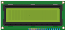
An LCD I2C 1602 screen is a type of liquid crystal display (LCD) that can be controlled using the I2C communication protocol. The « 1602 » in the name refers to the size of the screen, which has 16 columns and 2 rows of characters. An I2C interface allows multiple devices to communicate with each other using just two wires, SDA and SCL, to transfer data.
To connect an LCD I2C 1602 screen to an Arduino, you will need to connect the screen’s I2C SDA and SCL pins to the corresponding pins on the Arduino, and also connect the screen’s power and ground pins to the power and ground of the Arduino. Once the connections are made, you can use the Arduino to send commands to the screen to display text, numbers, or characters.
There are libraries available for the Arduino that make it easy to control an LCD I2C 1602 screen, such as the LiquidCrystal_I2C library which can be used to initialize the screen, set the cursor position, and print text and characters to the screen.
4×4 keypad
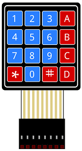
A 4×4 keypad is a type of input device that consists of 16 buttons arranged in a 4×4 grid. It can be used to provide a convenient way for a user to input data or commands into an Arduino-controlled system.
To connect a 4×4 keypad to an Arduino, you will need to connect the keypad’s rows and columns to the Arduino‘s digital input/output pins. The keypad typically has eight pins, four for the rows and four for the columns. The rows are connected to the Arduino‘s digital output pins and the columns are connected to the Arduino’s digital input pins.
Once the connections are made, you can use the Arduino to read the state of the keypad’s buttons by scanning the columns and reading the state of the rows. The Arduino can then determine which button is pressed by using a combination of the row and column states.
There are libraries available for the Arduino that make it easy to read a 4×4 keypad, such as the Keypad library, which can be used to initialize the keypad and read the state of the buttons.
battery of 9V
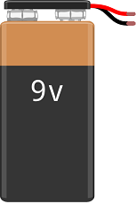
A 9V battery is a type of primary (non-rechargeable) battery that provides a nominal voltage of 9 volts. It is commonly used in portable devices such as smoke detectors, remote controls, and small electronic toys. 9V batteries are also used in some low-power projects such as small robots and simple electronic circuits.
Test plate
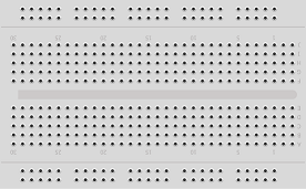
A test plate for Arduino is a type of test plate that can be used in conjunction with an Arduino microcontroller to automate experiments or tests. The test plate typically contains multiple wells or compartments that can hold samples or test solutions, and is designed to interface with the Arduino’s digital inputs and outputs.
Connecting wires

Wires in a robotic system are used to connect and transmit electrical signals between different components of the robot. These components can include sensors, actuators, motors, and the microcontroller, such as an Arduino. The wires in a robotic system are typically made of copper and are insulated to prevent electrical interference and short circuits.
The type of wires used in a robotic system depends on the specific application and requirements of the robot. For example, a robot that requires high-current power transmission may use thicker, high-gauge wires, while a robot that requires a high degree of flexibility and movement may use thinner, more flexible wires.
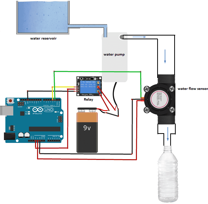
Assembly of the Arduino board with the water pump and the water flow sensor:
The relay is the intermediate component between the Arduino board and the water pump. It allows the Arduino board to control the water pump.
The role of the relay is to start or stop the pump responsible for filling the bottles.
We connect:
-
the (-) terminal of the relay to the GND pin of the Arduino
-
the (+) terminal of the relay to the 3.3V pin of the Arduino
-
terminal (S) of the relay to pin N°3 of the Arduino
the role of the yf-s401 sensor is to measure water flow during filling.
We connect :
-
The red wire to the 5V pin of the Arduino
-
the black wire to the GND pin of the Arduino
-
the yellow wire to pin N°2 of the Arduino
Assembly of the Arduino board with the matrix keyboard:
The matrix keyboard is the intermediate component between the Arduino board and the user. It is used to enter the value of the volume of water to fill in the bottle.

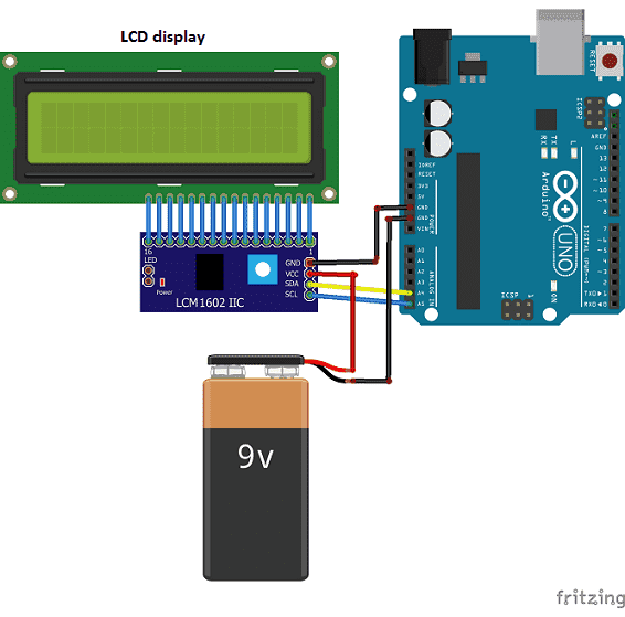
Assembly of the Arduino board with the I2C LCD 1602A display:
The 1602A I2C LCD display is used to display: the volume value entered by the user, the water flow rate and the amount of water filled in the bottle.
We connect:
-
the SDA pin of the LCD display to PIN 4 of the Arduino
-
the SCL pin of the LCD display to PIN 5 of the Arduino
-
the GND pin of the LCD display to the GND pin of the Arduino
-
the VCC pin of the LCD display to the (+) terminal of a 9V battery
Arduino program
Here is the program that allows you to control the filling of the bottle by the Arduino card.
|
1 2 3 4 5 6 7 8 9 10 11 12 13 14 15 16 17 18 19 20 21 22 23 24 25 26 27 28 29 30 31 32 33 34 35 36 37 38 39 40 41 42 43 44 45 46 47 48 49 50 51 52 53 54 55 56 57 58 59 60 61 62 63 64 65 66 67 68 69 70 71 72 73 74 75 76 77 78 79 80 81 82 83 84 85 86 87 88 89 90 91 92 93 94 95 96 97 98 99 100 101 102 103 104 105 106 107 108 109 110 111 112 113 114 115 116 117 118 119 120 121 122 123 124 125 126 127 128 129 130 131 132 133 134 135 136 137 138 139 140 141 142 143 144 145 146 147 148 149 150 151 152 153 154 155 156 157 |
#include <Keypad.h> #include <LiquidCrystal_I2C.h> const int ROW_NUM = 4; //four rows const int COLUMN_NUM = 4; //four columns char keys[ROW_NUM][COLUMN_NUM] = { {'1','2','3', 'A'}, {'4','5','6', 'B'}, {'7','8','9', 'C'}, {'*','0','#', 'D'} }; LiquidCrystal_I2C lcd(0x27, 20, 4); // ligne 8 byte pin_rows[ROW_NUM] = {11, 10, 9, 8}; //connect to the row pinouts of the keypad byte pin_column[COLUMN_NUM] = {7, 6, 5, 4}; //connect to the column pinouts of the keypad Keypad keypad = Keypad( makeKeymap(keys), pin_rows, pin_column, ROW_NUM, COLUMN_NUM ); int sensorInterrupt = 0; // interrupt 0 int sensorPin = 2; //Digital Pin 2 int solenoidValve = 5; // Digital pin 5 unsigned int SetPoint = 400; //400 milileter String code=""; /*The hall-effect flow sensor outputs pulses per second per litre/minute of flow.*/ float calibrationFactor = 90; //You can change according to your datasheet volatile byte pulseCount =0; float flowRate = 0.0; unsigned int flowMilliLitres =0; unsigned long totalMilliLitres = 0,volume=0; unsigned long oldTime ; const int relais_moteur = 3; // the relay is connected to pin 3 of the Adruino board void setup() { totalMilliLitres = 0; pinMode(relais_moteur, OUTPUT); lcd.init(); // display initialization lcd.clear(); lcd.backlight(); // activate the backlight lcd.setCursor(0, 0); // stand in the front line lcd.print("donner volume:"); // Initialize a serial connection for reporting values to the host Serial.begin(9600); pinMode(solenoidValve , OUTPUT); digitalWrite(solenoidValve, HIGH); pinMode(sensorPin, INPUT); digitalWrite(sensorPin, HIGH); /*The Hall-effect sensor is connected to pin 2 which uses interrupt 0. Configured to trigger on a FALLING state change (transition from HIGH (state to LOW state)*/ attachInterrupt(sensorInterrupt, pulseCounter, FALLING); //you can use Rising or Falling } void loop() { char key = keypad.getKey(); //lcd.clear(); if(key) // A key on the keyboard is pressed { code+=key; lcd.setCursor(0, 1); // stand on the second line lcd.print(code); // show volume value delay(100); } if (key=='D') { // if you press the 'D' key if(code.toInt()<=1500){ volume=code.toInt(); } else{ lcd.clear(); lcd.backlight(); lcd.setCursor(0, 0); lcd.print("donner volume:"); } code=""; } if (totalMilliLitres<volume) { digitalWrite(relais_moteur, HIGH); // Start the water pump if((millis() - oldTime) > 1000) // Only process counters once per second { // Disable the interrupt while calculating flow rate and sending the value to the host detachInterrupt(sensorInterrupt); // Because this loop may not complete in exactly 1 second intervals we calculate the number of milliseconds that have passed since the last execution and use that to scale the output. We also apply the calibrationFactor to scale the output based on the number of pulses per second per units of measure (litres/minute in this case) coming from the sensor. flowRate = ((1000.0 / (millis() - oldTime)) * pulseCount) / calibrationFactor; // Note the time this processing pass was executed. Note that because we've // disabled interrupts the millis() function won't actually be incrementing right // at this point, but it will still return the value it was set to just before // interrupts went away. oldTime = millis(); // Divide the flow rate in litres/minute by 60 to determine how many litres have // passed through the sensor in this 1 second interval, then multiply by 1000 to // convert to millilitres. flowMilliLitres = (flowRate / 60) * 1000; // Add the millilitres passed in this second to the cumulative total totalMilliLitres += flowMilliLitres; unsigned int frac; // Print the flow rate for this second in litres / minute Serial.print("Flow rate: "); Serial.print(flowMilliLitres, DEC); // Print the integer part of the variable Serial.print("mL/Second"); Serial.print("\t"); lcd.clear(); lcd.backlight(); lcd.setCursor(0, 0); lcd.print("debit:"); lcd.print(flowMilliLitres); // Show the flow rate on the lcd display lcd.print(" ml/s"); // Print the cumulative total of litres flowed since starting Serial.print("Output Liquid Quantity: "); Serial.print(totalMilliLitres,DEC); Serial.println("mL"); Serial.print("\t"); lcd.setCursor(0, 1); lcd.print("volume:"); lcd.print(totalMilliLitres); // Show quantity filled lcd.print(" ml"); if (totalMilliLitres > 40) { SetSolinoidValve(); } // Reset the pulse counter so we can start incrementing again pulseCount = 0; // Enable the interrupt again now that we've finished sending output attachInterrupt(sensorInterrupt, pulseCounter, FALLING); } }else { digitalWrite(relais_moteur, LOW); // Stop the water pump volume=0; } } //Insterrupt Service Routine void pulseCounter() { // Increment the pulse counter pulseCount++; } void SetSolinoidValve() { digitalWrite(solenoidValve, LOW); } |



Edwin 03-08-2222
hello sir, the article is good, i like it. but there are some things that i don't know between the code and the equipment, in the code there is a solenoid valve as well as a 20x4 lcd but the video doesn't include a solenoid valve and a 4x20 lcd