
Presentation of robot car
A robot car is a type of autonomous vehicle that is equipped with various sensors, actuators, and a computer or microcontroller to allow it to move and perform tasks without human intervention. Robot cars can be used for a variety of purposes, including transportation, scientific research, and entertainment.
Robot cars typically use a combination of sensors, such as cameras, lidars, radars, and ultrasonic sensors, to gather information about their surroundings. This information is then processed by the robot‘s computer or microcontroller, which determines the appropriate actions to take based on the information received. The robot car can then use actuators, such as motors, to control its movement and perform tasks.
Robot cars can be powered by a variety of sources, including batteries, gasoline, or electricity. They can also be equipped with various types of propulsion systems, such as wheels or tracks, to help them move on different types of terrain.
Robot cars can be designed for a variety of applications, including personal transportation, military missions, search and rescue operations, and delivery services. Some of the most advanced robot cars are even capable of driving themselves on public roads, although the use of autonomous vehicles for personal transportation is still a developing technology and is subject to various legal and regulatory restrictions.
Presentation of obstacle avoiding robot
An obstacle avoiding robot is a type of robot that is designed to navigate through its environment while avoiding obstacles that are in its path. This type of robot is equipped with sensors, such as ultrasound or infrared sensors, that allow it to detect obstacles and make decisions about how to navigate around them.
Obstacle avoiding robots are often used for educational purposes, as a demonstration of basic robotics principles, and as a platform for experimenting and innovating. They can also be used for practical purposes, such as cleaning floors or navigating through hazardous environments.
To build an obstacle avoiding robot, you typically need to start with a base platform, such as a two-wheeled or four-wheeled chassis. You will then need to add the necessary components, such as motors, a microcontroller or single-board computer, and the appropriate sensors.
Once the robot is assembled, you can program it to perform a variety of tasks, such as following a line, avoiding obstacles, or responding to signals from a remote control. You can also experiment with different types of sensors, actuators, and control algorithms to see how they impact the robot‘s behavior.
Presentation of obstacle avoiding robot using Arduino
An obstacle avoiding robot can be built using an Arduino microcontroller, which provides an easy-to-use platform for controlling the various components of the robot.
Here’s a basic overview of how to build an obstacle avoiding robot using an Arduino:
- Gather components: You will need an Arduino board, a motor driver, wheels or tracks, a power supply, and sensors for detecting obstacles. An HC-SR04 ultrasonic sensor is a popular choice for detecting obstacles.
- Connect the components: Connect the motors to the motor driver, which will control the speed and direction of the motors. Connect the power supply to the Arduino and the motor driver. Connect the HC-SR04 sensor to the Arduino and make sure it is positioned properly on the robot.
- Program the Arduino: Write the code for the robot using the Arduino Integrated Development Environment (IDE). The code will need to control the motors, read the data from the HC-SR04 sensor, and implement the obstacle avoidance logic.
- Test the robot: Upload the code to the Arduino and test the robot to make sure it is able to detect obstacles and avoid them. Adjust the code as needed to improve the performance of the robot.
- Assemble the robot: Once the code has been tested and the components are working as expected, assemble the robot by attaching the wheels or tracks, the motor driver, and the HC-SR04 sensor to a frame.
Obstacle avoiding robot using Arduino operation
The operation of an obstacle avoiding robot using an Arduino microcontroller involves several key steps:
- Sensing the environment: The HC-SR04 ultrasonic sensor is used to detect obstacles in the robot‘s environment. The sensor sends out a burst of ultrasound and measures the time it takes for the sound to bounce back, which is used to calculate the distance to the obstacle.
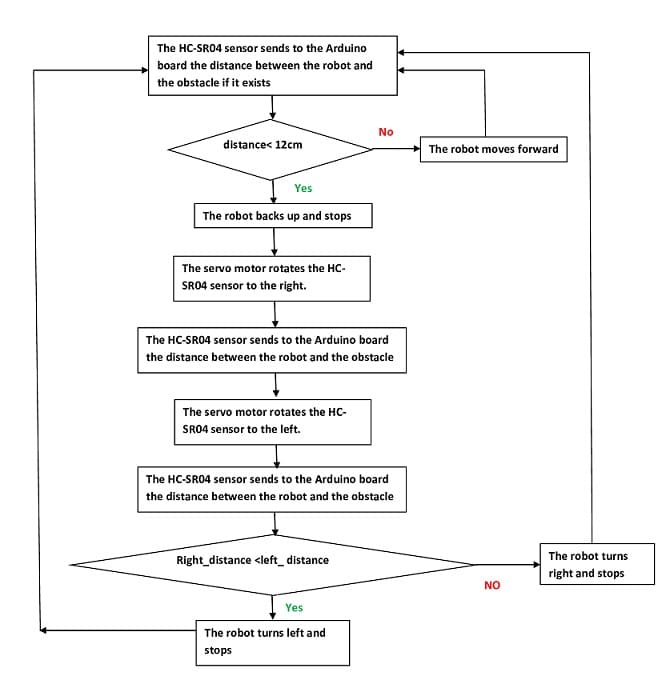
- Making decisions: Based on the distance readings from the HC-SR04 sensor, the Arduino code implements the obstacle avoidance logic. The code will determine whether there is an obstacle in front of the robot, and if so, it will make a decision about which direction to move to avoid the obstacle.
- Controlling the motors: The motor driver is used to control the speed and direction of the motors. The motor driver takes the control signals from the Arduino and applies them to the motors, which causes the robot to move.
- Repeating the process: The robot will continuously sense its environment and make decisions about which direction to move, creating a loop that repeats until the robot is turned off.
The necessary components
Arduino UNO

Arduino UNO is a microcontroller board based on the ATmega328P microcontroller. It is one of the most popular boards in the Arduino lineup and is widely used for a variety of projects, including robotics, home automation, and Internet of Things (IoT) applications.
The Arduino UNO has several key features, including:
- Microcontroller: The ATmega328P is an 8-bit microcontroller that provides the processing power for the board. It has 32 KB of flash memory for storing code, 2 KB of SRAM for data storage, and 1 KB of EEPROM for non-volatile storage.
- Input/Output (I/O) pins: The Arduino UNO has 14 digital input/output pins and 6 analog input pins, which can be used for a variety of purposes, such as reading sensors, controlling actuators, and communicating with other devices.
- USB connection: The Arduino UNO has a USB connection for programming and communication with a computer. The USB connection is also used to power the board.
- Power options: The Arduino UNO can be powered through the USB connection, or it can be powered by an external power supply, such as a battery.
- Easy to use: The Arduino UNO is designed to be easy to use, with a user-friendly software development environment and a large community of users and developers who share their projects and provide support.
The Arduino UNO is a versatile platform that can be used for a wide range of projects, from simple projects for beginners to complex projects for experienced users. Whether you’re just starting out with electronics and programming or you’re a seasoned maker, the Arduino UNO is a great choice for your next project.
Module L293D
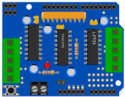
The L293D is a dual H-bridge motor driver integrated circuit (IC). It is used to control the speed and direction of DC motors, as well as to control the direction of stepper motors. The L293D can drive motors with a voltage range of 4.5 to 36 volts and can deliver up to 600 mA of current per channel.
The L293D has several key features, including:
- Dual H-bridge: The L293D has two independent H-bridge circuits, each of which can control the speed and direction of a single DC motor. This allows the L293D to control two motors with a single IC.
- Over-current protection: The L293D has built-in protection against over-current and thermal overload, which helps to prevent damage to the IC and the motors in the event of a fault.
- Simple control signals: The L293D uses simple digital signals to control the speed and direction of the motors. The direction of each motor is controlled by two signals (IN1 and IN2 for one motor, and IN3 and IN4 for the other), and the speed of each motor is controlled by a pulse-width modulation (PWM) signal.
- Wide voltage range: The L293D can be used with a wide range of DC power supplies, from 4.5 to 36 volts, which makes it suitable for use in a variety of applications.
The L293D is a popular choice for controlling motors in a variety of projects, including robots, remote-controlled vehicles, and automated systems. It is a versatile IC that provides a simple and reliable way to control DC motors, making it an ideal choice for many applications.
The L293D module can be used to control the motors in a robot car. A robot car typically consists of a microcontroller (such as an Arduino), a power supply (such as a battery), motors, wheels, and various sensors (such as distance sensors, line-following sensors, or infrared sensors).
To use the L293D module in a robot car, the module is connected to the microcontroller and the motors. The microcontroller provides the control signals to the L293D, which in turn drives the motors. The L293D allows the microcontroller to control the speed and direction of the motors, which can be used to navigate the robot car around obstacles and reach its destination.
The L293D is a simple and reliable way to control motors in a robot car, and it can be used with a wide range of microcontrollers, sensors, and power supplies. With its wide voltage range and high current capacity, the L293D is well-suited for use in a variety of robotic applications, including obstacle avoidance, line following, and autonomous navigation.
Capteur HC-SR04
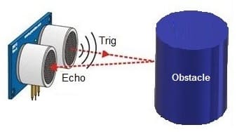
Le capteur HC-SR04 est un capteur de distance ultrasonique utilisé fréquemment dans les projets de robotique pour mesurer les distances à des objets. Il fonctionne en émettant un signal ultrasonique et en mesurant le temps qu’il faut pour que l’écho revienne au capteur. En utilisant la vitesse du son et le temps de voyage aller-retour, le capteur peut déterminer la distance à un objet.
Le capteur HC-SR04 est facile à utiliser et à intégrer dans des projets de robotique, car il dispose de quatre fils : alimentation, masse, déclenchement et écho. Il peut être contrôlé par une variété de contrôleurs électroniques, tels que la carte Arduino.
Les capteurs HC-SR04 sont utiles pour les robots qui doivent éviter les obstacles ou naviguer dans un environnement. Ils peuvent également être utilisés pour détecter les objets en mouvement, pour mesurer les distances à des objets, etc.
En résumé, le capteur HC-SR04 est un capteur de distance ultrasonique utile pour les projets de robotique qui nécessitent une mesure de distance à des objets. Il est facile à utiliser et à intégrer dans des projets grâce à ses quatre fils de connexion simples.
Servo motor

The HC-SR04 is a type of ultrasonic sensor that is commonly used for distance measurement and object detection. The sensor uses sound waves to determine the distance to an object by measuring the time it takes for an ultrasound signal to travel from the sensor to the object and back.
The HC-SR04 sensor consists of two main components: a transmitting unit (the « trigger ») and a receiving unit (the « echo »). The trigger sends out a short ultrasonic pulse, and the echo receives the reflected pulse from an object. By measuring the time between the trigger and the echo, the sensor can calculate the distance to the object.
The HC-SR04 sensor can be used in a wide range of applications, including obstacle avoidance in robotics, distance sensing in automation, and proximity detection in security systems. The sensor is relatively easy to use and can be interfaced with microcontrollers such as the Arduino, making it a popular choice for DIY projects.
The sensor can measure distances between 2 cm and 400 cm, with a typical accuracy of 3mm. It is important to keep in mind that the accuracy of the measurements can be affected by factors such as the reflectivity of the objects and the presence of ambient noise.
5V DC motor
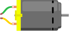
A 5V DC motor is a type of direct current (DC) motor that operates on 5 volts of power. DC motors are commonly used in a variety of applications, including robotics, toys, and small appliances.
The 5V DC motor typically has two terminals: one for the positive voltage and one for the negative voltage. When the voltage is applied to the terminals, the motor will start to rotate. The direction of rotation and the speed of the motor can be controlled by reversing the polarity of the voltage applied to the terminals.
5V DC motors are often used in small and lightweight applications due to their low power consumption and small size. However, they typically have lower torque and speed compared to higher voltage DC motors, making them less suitable for applications that require a lot of power or speed.
9V Battery
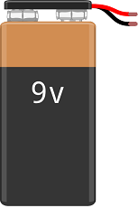
A 9V battery is a type of rectangular, cylindrical battery that is commonly used in a variety of portable devices and electronics. It is commonly referred to as a « transistor battery » because it was originally designed for use in transistor radios.
9V batteries have a nominal voltage of 9 volts and are made up of six individual 1.5V cells connected in series. They are often used in devices that require a compact and portable power source, such as smoke detectors, portable radios, and handheld games.
Fils de connexion
Connecting wires are electrical wires used to connect various electrical components in a circuit. They are an essential component of any electrical or electronic system, as they are used to transfer electrical energy and signals between the different parts of the circuit.
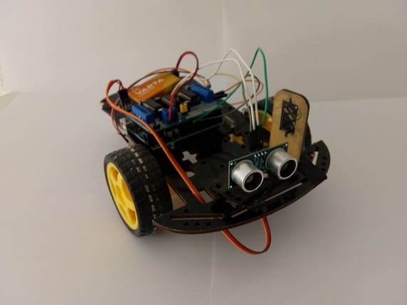
2 wheel car robot kit
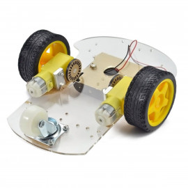
A 2 wheel car robot kit is a kit designed to help you build a small, two-wheeled robot. The kit typically includes all of the components you need to assemble the robot, such as wheels, motors, a microcontroller, a battery, and a set of sensors and actuators.
These kits are often used for educational purposes, to teach individuals about robotics and electronics. They can also be used for hobby projects and as a platform for experimentation and innovation.
The exact components included in a 2 wheel car robot kit can vary, but they typically include a microcontroller or single-board computer, such as an Arduino or Raspberry Pi, a pair of DC motors, wheels, and a battery for power. The kit may also include additional components such as sensors, such as infrared or ultrasonic sensors, and actuators, such as LEDs or buzzers.
To build the robot, you typically need to follow a set of instructions and assemble the components according to the design provided. Once the robot is assembled, you can program it to perform a variety of tasks, such as following a line, avoiding obstacles, or responding to signals from a remote control.
Overall, 2 wheel car robot kits are a fun and educational way to learn about robotics and electronics. Whether you are a beginner or an experienced hobbyist, these kits can provide you with a fun and engaging platform for exploring the world of robotics.
Pour assembler les composants du kit robot, vous pouvez voir cette vidéo.
Assembly of the robot
The assembly of an obstacle avoiding robot using an Arduino involves several steps, including:
- Gather the components: You will need an Arduino board (such as an Arduino UNO), a L293D motor driver module, a power supply (such as a battery), DC motors, wheels, an HC-SR04 ultrasonic distance sensor, and various other components, such as wires, connectors, and a chassis for the robot.
- Build the chassis: You can use materials such as plastic, cardboard, or metal to build the chassis for your robot. The chassis should be sturdy enough to support the motors, sensors, and other components.
- Connect the motors to the L293D: The DC motors are connected to the L293D motor driver module, which is used to control the speed and direction of the motors. The L293D is connected to the power supply, and the motor connections are made according to the manufacturer’s instructions.
- Connect the HC-SR04 sensor: The HC-SR04 ultrasonic distance sensor is connected to the Arduino board. The sensor is used to detect obstacles in the robot‘s path and to determine the distance to the nearest obstacle.
- Connect the power supply: The power supply, such as a battery, is connected to the Arduino board and the L293D module. The power supply provides the power needed to run the motors and the sensors.
- Upload the code: The code for the obstacle avoiding robot is uploaded to the Arduino board using the Arduino Integrated Development Environment (IDE). The code reads the distance measurements from the HC-SR04 sensor and uses that information to control the speed and direction of the motors.
- Test the robot: Once the robot is assembled and the code is uploaded, it can be tested to ensure that it is functioning properly. You can adjust the code as needed to improve the performance of the robot and make any necessary changes to the hardware.
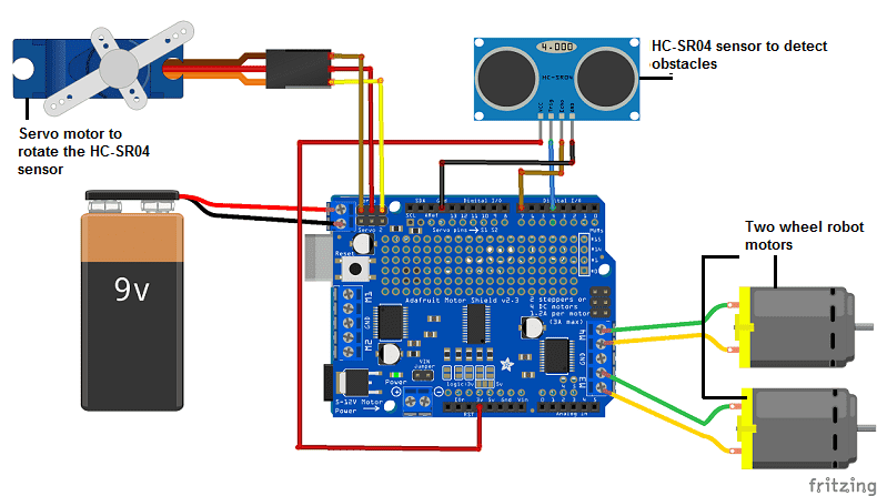
1- For the HC-SR04 sensor we connect
-
The GND terminal of the sensor to the GND pin of the Arduino board
-
The VCC terminal of the sensor to the 3.3V pin of the Arduino board
-
The ECHO terminal of the sensor to pin N°7 of the Arduino board
-
The TRIG terminal of the sensor to pin N°4 of the Arduino board
2- Connect the L293D module to the Arduino board
3- We connect the servo motor to the L293D module
Arduino Program
Here is the robot program controlled by the Arduino UNO board which detects and avoids obstacles using an ultrasonic distance sensor.
You need to import these two libraries: hcsr04 and AFMotor
|
1 2 3 4 5 6 7 8 9 10 11 12 13 14 15 16 17 18 19 20 21 22 23 24 25 26 27 28 29 30 31 32 33 34 35 36 37 38 39 40 41 42 43 44 45 46 47 48 49 50 51 52 53 54 55 56 57 58 59 60 61 62 63 64 65 66 67 68 69 70 71 72 73 74 |
#include <HCSR04.h> #include <AFMotor.h> #include <Servo.h> Servo myservo; // create servo object to control a servo AF_DCMotor motor1(3); // connect the two robot wheel motors to the L293D module AF_DCMotor motor2(4); // HC-SR04 sensor pin definition const int trigPin = 4; const int echoPin = 7; int distance,distance_droite,distance_gauche; int pos; // initialization of the sensor with the pins used. UltraSonicDistanceSensor distanceSensor(trigPin, echoPin); void setup() { myservo.write(90); // tell servo to go to position 90 myservo.attach(10); // attaches the servo on pin 10 to the servo object motor1.setSpeed(100); motor2.setSpeed(100); // initialisation du port serie a 9600 band pour afficher les valeurs mesurees par le capteur. Serial.begin(9600); } void loop() { distance = distanceSensor.measureDistanceCm(); Serial.println(distance); delay(50); if ((distance<15)and(distance>0)){ // the HC-SR04 sensor detects an obstacle motor1.run(RELEASE); // the robot stops motor2.run(RELEASE); delay(500); motor1.run(BACKWARD); // the robot is backing up motor2.run(BACKWARD); delay(500); motor1.run(RELEASE); // the robot stops motor2.run(RELEASE); for (pos = 90; pos > 10; pos -= 1) { // Faire tourner le capteur HC-SR04 vers la droite myservo.write(pos); delay(15); } delay(500); distance_droite = distanceSensor.measureDistanceCm(); // calculer la distance entre le capteur HC-SR04 et un obstacle s'il existe delay(500); for (pos = 0; pos < 170; pos += 1) { // Rotate the HC-SR04 sensor to the left // in steps of 1 degree myservo.write(pos); delay(15); } delay(500); distance_gauche = distanceSensor.measureDistanceCm();// calculate the distance between the HC-SR04 sensor and an obstacle if there is delay(500); for (pos = 170; pos > 90; pos -= 1) { // return to the initial position myservo.write(pos); delay(15); delay(500); } if (distance_droite<distance_gauche){ motor2.run(FORWARD); // turn the robot left delay(1000); motor2.run(RELEASE); delay(500); } else { motor1.run(FORWARD); // turn the robot right delay(1000); motor1.run(RELEASE); delay(500); } } else if (distance>0) { motor1.run(FORWARD); // move the car forward motor2.run(FORWARD); } } |

