
Radar (Radio Detection And Ranging) is a technology that uses radio waves to detect the range, speed, and angle of objects. It works by emitting a radio frequency (RF) signal and measuring the time it takes for the signal to bounce back from an object. The distance, speed, and angle of the object can be calculated by measuring the time it takes for the signal to travel to the object and back, and then using the speed of light to determine the distance.
Radar systems can be used for a wide range of applications, such as:
- Air and maritime navigation: radar systems are used to detect and track ships and airplanes.
- Weather forecasting: radar systems are used to detect precipitation, wind patterns and other weather conditions.
- Military applications: radar systems are used to detect and track aircraft, ships, and other military targets.
- Law enforcement: radar systems are used to detect and measure the speed of vehicles on the road.
- Industrial and scientific applications: radar systems are used to detect and measure the distance of objects in a variety of industrial and scientific applications such as in robotics, robotics and autonomous vehicles.
Radar systems can be classified into different types based on their operating frequency, such as X-band, S-band, and L-band radar. They can also be classified into different types based on their method of operation, such as pulse radar, continuous-wave radar, and frequency-modulated radar.
Objective of this project:
An Arduino microcontroller can be used in combination with a radar sensor to send data to a computer. The Arduino can be programmed to collect data from the radar sensor and then transmit the data to the computer via USB Serial Communication. The computer can then receive the data and process it using software.
To accomplish this, the Arduino board needs to be connected to a radar sensor, such as a HC-SR04 ultrasonic sensor. The sensor can be configured to emit a radio-frequency (RF) signal and measure the time it takes for the signal to bounce back from an object. The distance, speed, and angle of the object can be calculated by measuring the time it takes for the signal to travel to the object and back.
The Arduino can then be programmed to send the data collected from the radar sensor to the computer. On the computer side, a software program can be used to receive the data from the Arduino. The program can be written in a variety of languages such as Python, Java, or C#.
It’s a common way to create a wireless communication between an Arduino, a HC-SR04 ultrasonic sensor and a computer, it’s simple to set up and it doesn’t require a specific operating system.
In this project, we are going to design a project using the Arduino board and an ultrasonic sensor for detection.
This project aims to produce a prototype radar system that detects fixed and moving objects.
Operation of the radar controlled by Arduino:
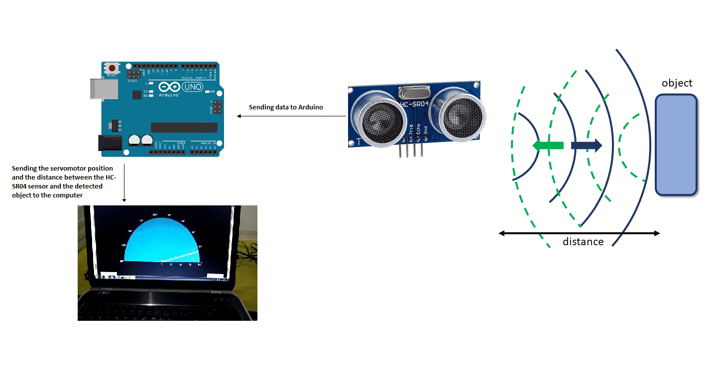
Components required
Arduino UNO

The Arduino UNO is a microcontroller board based on the ATmega328P microcontroller. It is one of the most popular boards in the Arduino family and is widely used for a variety of projects, from hobbyist and educational projects to professional applications.
The Arduino UNO has a variety of features that make it easy to use, including:
- A microcontroller: The ATmega328P microcontroller is a powerful and versatile chip that can be programmed using the Arduino programming language.
- Input/Output (I/O) pins: The board has 14 digital I/O pins and 6 analog input pins, which can be used to interface with a wide variety of sensors, actuators, and other devices.
- Power supply: The board can be powered by an external power supply or by USB. It has a voltage regulator that can accept a wide range of input voltage and provide a stable 5V output.
- Programming interface: The board has a USB-to-Serial converter that can be used to program the microcontroller and communicate with the computer.
- On-board LEDs and buttons: The board has two LEDs (RX and TX) and one reset button that can be used for debugging or testing purposes.
- Compatibility: The Arduino UNO is compatible with a wide range of shields and add-on boards, which can be used to add additional functionality to the board.
The Arduino UNO is an open-source platform and it’s easy to find tutorials, sample codes, and libraries. It’s a good choice for beginners and also for more advanced projects, it’s widely supported by the community and it’s easy to find. It’s also a great learning tool for those who want to start with electronics and programming.
HC-SR04 sensor
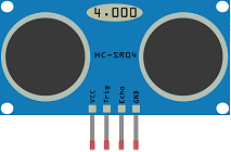
The HC-SR04 is a popular ultrasonic sensor that can be used to implement a basic radar system with an Arduino microcontroller. This sensor uses ultrasonic waves, which are sound waves with a frequency higher than the upper limit of human hearing, to measure distance.
To use the HC-SR04 sensor with an Arduino, it needs to be connected to the Arduino’s digital pins. The sensor has four pins: Vcc, Trig, Echo and GND. The Vcc and GND pins are used to power the sensor, the Trig pin is used to trigger the sensor to send out an ultrasonic pulse, and the Echo pin is used to receive the reflected pulse.
The Arduino can be programmed to send a trigger signal to the Trig pin, and then measure the time it takes for the Echo pin to receive the reflected pulse. This time can be used to calculate the distance to an object.
The HC-SR04 sensor has a range of 2cm to 400cm and it’s accurate within 3mm. It can be used to detect and measure the distance of objects in a variety of applications, such as robotics, autonomous vehicles, and obstacle avoidance systems.
It’s a simple and low-cost way to add a distance measuring capability to an Arduino project, it’s easy to set up and it doesn’t require any additional components. However, it’s important to note that the sensor is affected by sound reflections and can give false readings, especially in noisy environments.
Servomotor

A servomotor is a type of motor that can be used to control the position of an object, such as a basic radar. To move the HC-SR04 using a servomotor, you would need to connect the servomotor to the sensor and use control signals to rotate the servomotor and move the sensor to different positions. The control signals can be generated using a microcontroller or a computer. The distance measurements can be taken by the HC-SR04 and sent to the Arduino UNO.
Connecting wires

Wires are used to transmit electrical signals and power to various components such as motors, sensors, and microcontrollers. It’s important to properly route and secure the wires to prevent tangles and damage. There are several methods for doing this, including using cable ties, clamps, and wire looms. It’s also a good idea to use different colors or labeling to identify the different wires and their functions. When connecting wires in a robot, it’s important to follow proper safety procedures, such as using the correct wire stripper and connectors, and wearing protective equipment such as gloves and safety glasses.
Assembly:
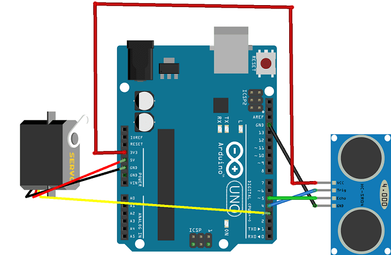
To do the editing, we connected:
For the HC-SR04 sound sensor:
-
the VCC pin to the 3.3V pin of the Arduino
-
the Trig pin to pin 4 of the Arduino
-
the ECHO pin to pin 5 of the Arduino
-
the GND pin to the GND pin of the Arduino
For the servomotor:
-
red wire: power supply wire to connect to the 5V terminal of the Arduino
-
brown wire: wire to connect to the GND pin of the Arduino
-
Yellow: Positioning signal wire connected to pin 3 of the Arduino
Arduino program
Here is the program that allows you to:
-
calculate the distance between the HC-SR04 sensor and the detected object
-
turn the servomotor
-
send data (servo motor position and distance) from the Arduino board to the computer.
|
1 2 3 4 5 6 7 8 9 10 11 12 13 14 15 16 17 18 19 20 21 22 23 24 25 26 27 28 29 30 31 32 33 34 35 36 37 38 39 40 41 42 43 44 45 46 47 48 |
#include <Servo.h> Servo servo_1; // servo controller (multiple can exist) int trig = 4; // trig pin for HC-SR04 int echo = 5; // echo pin for HC-SR04 int servo_pin = 3; // PWM pin for servo control int pos = 0; // servo starting position float duration,distance; void setup() { Serial.begin(115200); Serial.println("Radar Start"); servo_1.attach(servo_pin); // start servo control pinMode(trig,OUTPUT); pinMode(echo,INPUT); } void loop() { for (pos = 0; pos <= 180; pos += 1) { // goes from 0 degrees to 180 degrees // in steps of 1 degree servo_1.write(pos); // tell servo to go to position in variable 'pos' delay(60); // delay to allow the servo to reach the desired position dist_calc(pos); } for (pos = 180; pos >= 0; pos -= 1) { // goes from 180 degrees to 0 degrees servo_1.write(pos); // tell servo to go to position in variable 'pos' delay(60); dist_calc(pos); } } float dist_calc(int pos){ // trigger 40kHz pulse for ranging digitalWrite(trig,LOW); delayMicroseconds(2); digitalWrite(trig,HIGH); delayMicroseconds(10); digitalWrite(trig,LOW); // convert from duration for pulse to reach detector (microseconds) to range (in cm) duration = pulseIn(echo,HIGH); // duration for pulse to reach detector (in microseconds) distance = 100.0*(343.0*(duration/2.0))/1000000.0; // 100.0*(speed of sound*duration/2)/microsec conversion Serial.print(pos); // position of servo motor Serial.print(","); // comma separate variables Serial.println(distance); // print distance in cm } |
Python program executed by the computer
|
1 2 3 4 5 6 7 8 9 10 11 12 13 14 15 16 17 18 19 20 21 22 23 24 25 26 27 28 29 30 31 32 33 34 35 36 37 38 39 40 41 42 43 44 45 46 47 48 49 50 51 52 53 54 55 56 57 58 59 60 61 62 63 64 65 66 67 68 69 70 71 72 73 74 75 76 77 78 79 80 81 82 83 84 85 86 87 88 89 90 91 92 93 94 95 96 97 98 99 100 101 102 103 104 105 106 107 108 109 110 111 112 113 114 115 116 117 118 119 120 121 122 123 124 125 126 127 128 129 130 131 132 133 134 135 136 137 138 139 140 141 142 143 144 145 146 147 148 149 150 151 152 153 154 155 156 157 |
# Python + Arduino-based Radar Plotter # # ** Works with any motor that outputs angular rotation # ** and with any distance sensor (HC-SR04, VL53L0x,LIDAR) # import numpy as np import matplotlib matplotlib.use('TkAgg') import matplotlib.pyplot as plt from matplotlib.widgets import Button import serial,sys,glob import serial.tools.list_ports as COMs # # ############################################ # Find Arudino ports, select one, then start communication with it ############################################ # def port_search(): if sys.platform.startswith('win'): # Windows ports = ['COM{0:1.0f}'.format(ii) for ii in range(1,256)] elif sys.platform.startswith('linux') or sys.platform.startswith('cygwin'): ports = glob.glob('/dev/tty[A-Za-z]*') elif sys.platform.startswith('darwin'): # MAC ports = glob.glob('/dev/tty.*') else: raise EnvironmentError('Machine Not pyserial Compatible') arduinos = [] for port in ports: # loop through to determine if accessible if len(port.split('Bluetooth'))>1: continue try: ser = serial.Serial(port) ser.close() arduinos.append(port) # if we can open it, consider it an arduino except (OSError, serial.SerialException): pass return arduinos arduino_ports = port_search() ser = serial.Serial(arduino_ports[0],baudrate=115200) # match baud on Arduino ser.flush() # clear the port # ############################################ # Start the interactive plotting tool and # plot 180 degrees with dummy data to start ############################################ # fig = plt.figure(facecolor='k') win = fig.canvas.manager.window # figure window screen_res = win.wm_maxsize() # used for window formatting later dpi = 150.0 # figure resolution fig.set_dpi(dpi) # set figure resolution # polar plot attributes and initial conditions ax = fig.add_subplot(111,polar=True,facecolor='#006d70') ax.set_position([-0.05,-0.05,1.1,1.05]) r_max = 100.0 # can change this based on range of sensor ax.set_ylim([0.0,r_max]) # range of distances to show ax.set_xlim([0.0,np.pi]) # limited by the servo span (0-180 deg) ax.tick_params(axis='both',colors='w') ax.grid(color='w',alpha=0.5) # grid color ax.set_rticks(np.linspace(0.0,r_max,5)) # show 5 different distances ax.set_thetagrids(np.linspace(0.0,180.0,10)) # show 10 angles angles = np.arange(0,181,1) # 0 - 180 degrees theta = angles*(np.pi/180.0) # to radians dists = np.ones((len(angles),)) # dummy distances until real data comes in pols, = ax.plot([],linestyle='',marker='o',markerfacecolor = 'w', markeredgecolor='#EFEFEF',markeredgewidth=1.0, markersize=10.0,alpha=0.9) # dots for radar points line1, = ax.plot([],color='w', linewidth=4.0) # sweeping arm plot # figure presentation adjustments fig.set_size_inches(0.96*(screen_res[0]/dpi),0.96*(screen_res[1]/dpi)) plot_res = fig.get_window_extent().bounds # window extent for centering win.wm_geometry('+{0:1.0f}+{1:1.0f}'.\ format((screen_res[0]/2.0)-(plot_res[2]/2.0), (screen_res[1]/2.0)-(plot_res[3]/2.0))) # centering plot fig.canvas.toolbar.pack_forget() # remove toolbar for clean presentation fig.canvas.set_window_title('Arduino Radar') fig.canvas.draw() # draw before loop axbackground = fig.canvas.copy_from_bbox(ax.bbox) # background to keep during loop ############################################ # button event to stop program ############################################ def stop_event(event): global stop_bool stop_bool = 1 prog_stop_ax = fig.add_axes([0.85,0.025,0.125,0.05]) pstop = Button(prog_stop_ax,'Stop Program',color='#FCFCFC',hovercolor='w') pstop.on_clicked(stop_event) # button to close window def close_event(event): global stop_bool,close_bool if stop_bool: plt.close('all') stop_bool = 1 close_bool = 1 close_ax = fig.add_axes([0.025,0.025,0.125,0.05]) close_but = Button(close_ax,'Close Plot',color='#FCFCFC',hovercolor='w') close_but.on_clicked(close_event) fig.show() ############################################ # inifinite loop, constantly updating the # 180deg radar with incoming Arduino data ############################################ # start_word,stop_bool,close_bool = False,False,False while True: try: if stop_bool: # stops program fig.canvas.toolbar.pack_configure() # show toolbar if close_bool: # closes radar window plt.close('all') break ser_bytes = ser.readline() # read Arduino serial data decoded_bytes = ser_bytes.decode('utf-8') # decode data to utf-8 data = (decoded_bytes.replace('\r','')).replace('\n','') #print(data.split(',')) if start_word: vals = [float(ii) for ii in data.split(',')] print(vals) if len(vals)<2: continue angle,dist = vals # separate into angle and distance if dist>r_max: dist = 0.0 # measuring more than r_max, it's likely inaccurate dists[int(angle)] = dist if angle % 5 ==0: # update every 5 degrees pols.set_data(theta,dists) fig.canvas.restore_region(axbackground) ax.draw_artist(pols) line1.set_data(np.repeat((angle*(np.pi/180.0)),2), np.linspace(0.0,r_max,2)) ax.draw_artist(line1) fig.canvas.blit(ax.bbox) # replot only data fig.canvas.flush_events() # flush for next plot else: if data=='Radar Start': # stard word on Arduno start_word = True # wait for Arduino to output start word print('Radar Starting...') else: continue except KeyboardInterrupt: plt.close('all') print('Keyboard Interrupt') break |

