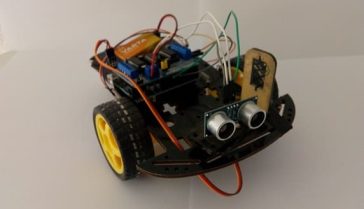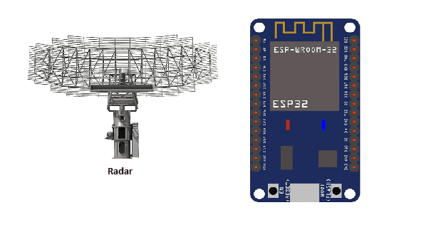

Radar (Radio Detection and Ranging) is a technology used to detect and locate objects by emitting radio waves and measuring the reflected waves that are bounced back. It works by sending out a radio frequency (RF) signal and then measuring the time it takes for the signal to be reflected back to the radar antenna. The distance to the object can be determined by measuring the time it takes for the signal to travel to the object and back.
Radar can be used for a wide variety of applications, including air and sea navigation, weather forecasting, and military and law enforcement operations. It is also commonly used in civilian applications such as traffic control, speed detection, and collision avoidance systems in cars.
There are different types of radar systems, each with different characteristics and uses. Some examples include:
- Pulse radar: emits a short burst of radio waves, which reflects off the target and returns back to the radar antenna.
- Continuous wave radar: emits a continuous radio wave, and by measuring the Doppler shift in frequency of the reflected wave, it can determine the target’s speed.
- FMCW radar (Frequency Modulated Continuous Wave): similar to continuous wave radar but the transmitted frequency is continuously varied. It’s widely used in radar altimeter, distance measuring and also in Automotive radar.
- Synthetic Aperture Radar (SAR): uses the motion of the radar antenna over a target to provide high-resolution images of the target.
It is a widely used technology with many different applications, and it continues to evolve with new technologies and innovations.
It is possible to use an ESP32 microcontroller to control and interface with a radar sensor. The ESP32 can be used to send commands to the radar sensor, receive data from it, and process the data. The ESP32 can be programmed to perform tasks such as rangefinding, target tracking, and obstacle detection, depending on the capabilities of the specific radar sensor being used.
One example of a radar sensor that can be used with the ESP32 is the Ultra-Wideband (UWB) radar sensor. This type of sensor uses a very narrow RF pulse, which allows for high-precision rangefinding and target tracking. The ESP32 can be used to send commands to the UWB radar sensor, receive the range measurements and then use that data to calculate the position of a target.
Another example is the radar sensors used in the Automotive radar, which are based on the FMCW (Frequency Modulated Continuous Wave) principle. The ESP32 can be used to send commands to the sensor, receive the data and process it to detect the distance, speed and angle of other vehicles or obstacles.
The ESP32 also has built-in support for USB Serial Communication , which can be used to transmit the radar data to other devices, such as a computer or smartphone, for further processing or display.
There are several ways to send data from an ESP32 microcontroller to a computer, depending on the specific requirements of the project and the capabilities of the computer. Some common methods include:
- USB Serial Communication: The ESP32 can be connected to a computer via a USB cable and configured to act as a serial device. The computer can then use a serial terminal program to receive and send data to the ESP32. This method is simple and easy to set up, but it has a limited data transfer rate.
- Wi-Fi: The ESP32 can be configured as a Wi-Fi client and connect to an existing Wi-Fi network. Once connected, the ESP32 can send data to the computer by opening a socket and sending the data to the computer’s IP address. This method allows for faster data transfer rates and greater flexibility, but it requires a Wi-Fi network to be available.
- Bluetooth: The ESP32 has built-in Bluetooth capabilities, it can be configured as a Bluetooth client and send data to a computer that is running a Bluetooth server. This method allows for low power consumption and low data transfer rates.
- MQTT: The ESP32 can be configured to send data to a computer using the MQTT protocol, which is a lightweight messaging protocol for the Internet of Things (IoT) applications. This method requires a MQTT broker to be set up on the computer and it’s useful when the ESP32 is sending data to multiple devices or when the connection is unreliable.
- HTTP: The ESP32 can be configured to send data over HTTP to a webserver running on a computer. This method can be useful when the data needs to be accessed over the internet or when the data needs to be stored in a database.
In all the above methods, the ESP32 needs to be programmed to send the data in a specific format and the computer needs to be programmed to receive and process the data.
Objective of this project:
In this project, we are going to design a project using the ESP32 board and an ultrasonic sensor for detection.
This project aims to produce a prototype radar system that detects fixed and moving objects.
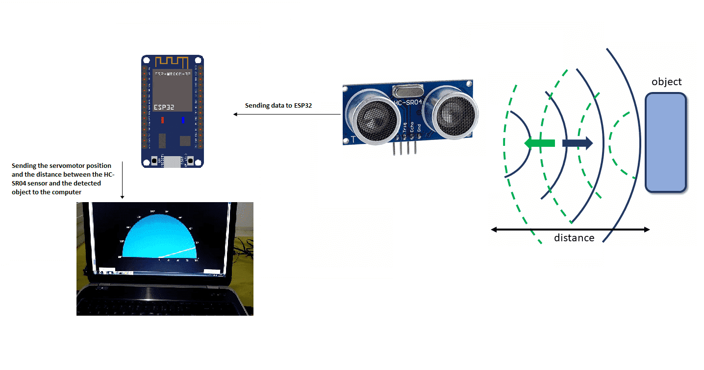
Operation of the radar controlled by ESP32:
Components required
ESP32 board
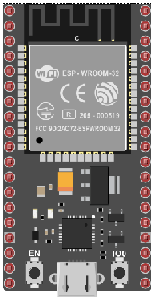
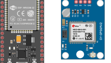
ESP32 is a series of low-cost, low-power system on a chip microcontrollers with integrated Wi-Fi and dual-mode Bluetooth. It was developed by Espressif Systems, a Shanghai-based Chinese company. The ESP32 chip is a powerful microcontroller that has a dual-core processor with a clock speed of up to 240 MHz, and it has a wide range of peripheral interfaces, such as I2C, SPI, UART, and ADC. It also has built-in support for Bluetooth and Wi-Fi, which makes it suitable for a wide range of IoT (Internet of Things) applications.
HC-SR04 sensor
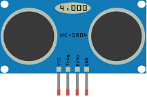
The HC-SR04 is an ultrasonic distance sensor that uses the principle of echolocation to determine the distance of an object. It works by emitting a high-frequency sound wave and measuring the time it takes for the sound wave to bounce back from an object. The distance of the object can be calculated by measuring the time it takes for the sound wave to travel to the object and back, and then using the speed of sound to determine the distance.
The HC-SR04 sensor includes an ultrasonic transmitter and receiver, and it can be used to measure distances up to 4 meters with an accuracy of 3mm. The sensor is inexpensive, small in size and easy to interface with a microcontroller like the ESP32.
The ESP32 can be used to trigger the HC-SR04 sensor to emit a sound wave, measure the time it takes for the sound wave to bounce back, and then calculate the distance of the object. The ESP32 can also be used to display the distance measurements on an LCD screen or send the data over a Wi-Fi or Bluetooth connection to another device.
It’s a popular choice for hobbyist and educational projects because of its low cost and ease of use. However, it has some limitations, such as not being able to detect objects behind walls or with a reflective surface, sensitivity to ambient noise and it’s not suitable for high-speed object detection.
Servomotor

A servomotor can be used to move the HC-SR04 ultrasonic distance sensor in order to provide a wider field of view or to scan an area for objects. A servo motor is a type of motor that can rotate to a specific position, and it can be controlled by sending a series of pulses to it.
To move the HC-SR04 sensor using a servo motor, the ESP32 microcontroller can be used to generate the control pulses for the servo motor. The ESP32 can send a series of pulses to the servo motor to rotate it to a specific position and then trigger the HC-SR04 sensor to emit a sound wave and measure the distance. The ESP32 can then repeat the process to rotate the servo motor to a different position and take another distance measurement.
This way, the servo motor can be programmed to rotate the HC-SR04 sensor through a range of angles, and the ESP32 can collect the distance measurements at each angle to create a 3D map of the environment.
connecting wires

Wires are used to transmit electrical signals and power to various components such as motors, sensors, and microcontrollers. It’s important to properly route and secure the wires to prevent tangles and damage. There are several methods for doing this, including using cable ties, clamps, and wire looms. It’s also a good idea to use different colors or labeling to identify the different wires and their functions. When connecting wires in a robot, it’s important to follow proper safety procedures, such as using the correct wire stripper and connectors, and wearing protective equipment such as gloves and safety glasses.
Test plate
An electronic test plate is a type of laboratory equipment that is used to hold and organize electronic components or printed circuit boards (PCBs) during testing or analysis. It is similar to a traditional test plate, but it is designed specifically for electronic components.
Assembly:
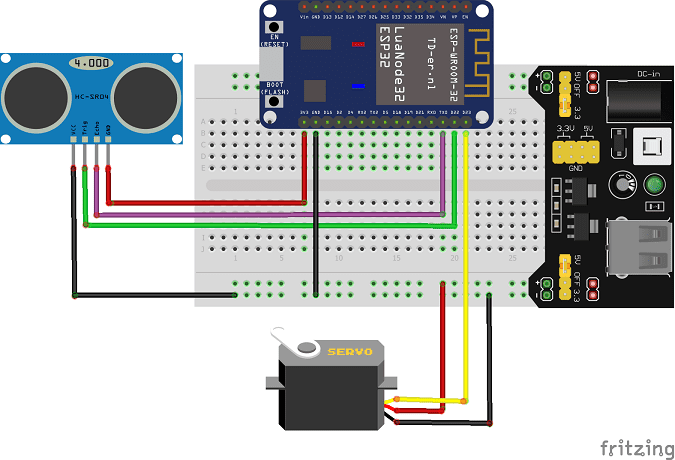
To do the editing, we connected:
For the HC-SR04 sound sensor:
-
the VCC pin to the 3.3V pin of ESP32
-
the Trig pin to pin D22 of ESP32
-
the ECHO pin to pin D21 of ESP32
-
the GND pin to the GND pin of ESP32
For the servomotor:
-
red wire: power supply wire to connect to 5V energy
-
brown wire: wire to connect to the GND pin of ESP32
-
Yellow: Positioning signal wire connected to pin D23 of ESP32
Micropython program
Here is the program that allows you to:
-
calculate the distance between the HC-SR04 sensor and the detected object
-
turn the servomotor
-
send data (servo motor position and distance) from the Arduino board to the computer.
Note: you must use these two libraries: hcsr04 and servo.
|
1 2 3 4 5 6 7 8 9 10 11 12 13 14 15 16 17 18 19 20 21 22 23 24 25 26 27 28 29 |
import machine from hcsr04 import HCSR04 from machine import UART,Pin from servo import Servo import utime # Initialize a UART objects uart = UART(2, baudrate=115200) sensor = HCSR04(trigger_pin=22,echo_pin=21,echo_timeout_us=1000000) servo_pin = machine.Pin(23) my_servo = Servo(servo_pin) delay = 0.01 min = 15 max = 165 count = 1 while True: for i in range(min,max): my_servo.write_angle(i) distance = sensor.distance_cm() if distance > 1000 : distance=0 print(i,',',distance) utime.sleep_ms(60) for i in range(max, min, -1): my_servo.write_angle(i) utime.sleep_ms(60) distance = sensor.distance_cm() if distance > 1000 : distance=0 print(i,',',distance) |
Python program executed by the computer
|
1 2 3 4 5 6 7 8 9 10 11 12 13 14 15 16 17 18 19 20 21 22 23 24 25 26 27 28 29 30 31 32 33 34 35 36 37 38 39 40 41 42 43 44 45 46 47 48 49 50 51 52 53 54 55 56 57 58 59 60 61 62 63 64 65 66 67 68 69 70 71 72 73 74 75 76 77 78 79 80 81 82 83 84 85 86 87 88 89 90 91 92 93 94 95 96 97 98 99 100 101 102 103 104 105 106 107 108 109 110 111 112 113 114 115 116 117 118 119 120 121 122 123 124 125 126 127 128 129 130 131 132 133 134 135 136 137 138 139 140 141 142 143 144 145 146 147 148 149 150 151 152 153 154 155 156 157 158 159 160 161 |
# Python + Arduino-based Radar Plotter # # ** Works with any motor that outputs angular rotation # ** and with any distance sensor (HC-SR04, VL53L0x,LIDAR) # import numpy as np import matplotlib matplotlib.use('TkAgg') import matplotlib.pyplot as plt from matplotlib.widgets import Button import serial,sys,glob import serial.tools.list_ports as COMs # # ############################################ # Find Arudino ports, select one, then start communication with it ############################################ # def port_search(): if sys.platform.startswith('win'): # Windows ports = ['COM{0:1.0f}'.format(ii) for ii in range(1,256)] elif sys.platform.startswith('linux') or sys.platform.startswith('cygwin'): ports = glob.glob('/dev/tty[A-Za-z]*') elif sys.platform.startswith('darwin'): # MAC ports = glob.glob('/dev/tty.*') else: raise EnvironmentError('Machine Not pyserial Compatible') arduinos = [] for port in ports: # loop through to determine if accessible if len(port.split('Bluetooth'))>1: continue try: ser = serial.Serial(port) ser.close() arduinos.append(port) # if we can open it, consider it an arduino except (OSError, serial.SerialException): pass return arduinos arduino_ports = port_search() #ser = serial.Serial(arduino_ports[0],baudrate=115200) # match baud on Arduino port1="COM4" ser = serial.Serial(port1,baudrate=115200) ser.flush() # clear the port # ############################################ # Start the interactive plotting tool and # plot 180 degrees with dummy data to start ############################################ # fig = plt.figure(facecolor='k') win = fig.canvas.manager.window # figure window screen_res = win.wm_maxsize() # used for window formatting later dpi = 150.0 # figure resolution fig.set_dpi(dpi) # set figure resolution # polar plot attributes and initial conditions ax = fig.add_subplot(111,polar=True,facecolor='#006d70') ax.set_position([-0.05,-0.05,1.1,1.05]) r_max = 100.0 # can change this based on range of sensor ax.set_ylim([0.0,r_max]) # range of distances to show ax.set_xlim([0.0,np.pi]) # limited by the servo span (0-180 deg) ax.tick_params(axis='both',colors='w') ax.grid(color='w',alpha=0.5) # grid color ax.set_rticks(np.linspace(0.0,r_max,5)) # show 5 different distances ax.set_thetagrids(np.linspace(0.0,180.0,10)) # show 10 angles angles = np.arange(0,181,1) # 0 - 180 degrees theta = angles*(np.pi/180.0) # to radians dists = np.ones((len(angles),)) # dummy distances until real data comes in pols, = ax.plot([],linestyle='',marker='o',markerfacecolor = 'w', markeredgecolor='#EFEFEF',markeredgewidth=1.0, markersize=10.0,alpha=0.9) # dots for radar points line1, = ax.plot([],color='w', linewidth=4.0) # sweeping arm plot # figure presentation adjustments fig.set_size_inches(0.96*(screen_res[0]/dpi),0.96*(screen_res[1]/dpi)) plot_res = fig.get_window_extent().bounds # window extent for centering win.wm_geometry('+{0:1.0f}+{1:1.0f}'.\ format((screen_res[0]/2.0)-(plot_res[2]/2.0), (screen_res[1]/2.0)-(plot_res[3]/2.0))) # centering plot fig.canvas.toolbar.pack_forget() # remove toolbar for clean presentation fig.canvas.set_window_title('Arduino Radar') fig.canvas.draw() # draw before loop axbackground = fig.canvas.copy_from_bbox(ax.bbox) # background to keep during loop ############################################ # button event to stop program ############################################ def stop_event(event): global stop_bool stop_bool = 1 prog_stop_ax = fig.add_axes([0.85,0.025,0.125,0.05]) pstop = Button(prog_stop_ax,'Stop Program',color='#FCFCFC',hovercolor='w') pstop.on_clicked(stop_event) # button to close window def close_event(event): global stop_bool,close_bool if stop_bool: plt.close('all') stop_bool = 1 close_bool = 1 close_ax = fig.add_axes([0.025,0.025,0.125,0.05]) close_but = Button(close_ax,'Close Plot',color='#FCFCFC',hovercolor='w') close_but.on_clicked(close_event) fig.show() ############################################ # inifinite loop, constantly updating the # 180deg radar with incoming Arduino data ############################################ # start_word,stop_bool,close_bool = True,False,False while True: try: if stop_bool: # stops program fig.canvas.toolbar.pack_configure() # show toolbar if close_bool: # closes radar window plt.close('all') break ser_bytes = ser.readline() # read Arduino serial data decoded_bytes = ser_bytes.decode('utf-8') # decode data to utf-8 #data =ser_bytes.decode('utf-8') print(decoded_bytes) data = (decoded_bytes.replace('\r','')).replace('\n','').replace(' ','') #print(data.split(',')) if start_word: vals = [float(ii) for ii in data.split(',')] print(vals) if len(vals)<2: continue angle,dist = vals # separate into angle and distance if dist>r_max: dist = 0.0 # measuring more than r_max, it's likely inaccurate dists[int(angle)] = dist if angle % 5 ==0: # update every 5 degrees pols.set_data(theta,dists) fig.canvas.restore_region(axbackground) ax.draw_artist(pols) line1.set_data(np.repeat((angle*(np.pi/180.0)),2), np.linspace(0.0,r_max,2)) ax.draw_artist(line1) fig.canvas.blit(ax.bbox) # replot only data fig.canvas.flush_events() # flush for next plot else: if data=='Radar Start': # stard word on Arduno start_word = True # wait for Arduino to output start word print('Radar Starting...') else: continue except KeyboardInterrupt: plt.close('all') print('Keyboard Interrupt') break |

