Using the 4×4 Matrix Keypad with Micro:bit

The Micro:bit is a small microcontroller board that is designed for use in educational settings. It can be programmed using a variety of programming languages, including MakeCode, Python, and JavaScript. It can be used to control motors, sense temperature, light, and other physical inputs, and can also be used to communicate with other devices wirelessly.
Interfacing a 4×4 matrix keypad with a Micro:bit is possible, but it would require some additional components and programming. The Micro:bit has a limited number of input/output pins, so you would need to use a device such as an I/O expander to connect the keypad.
Purpose of this tutorial:
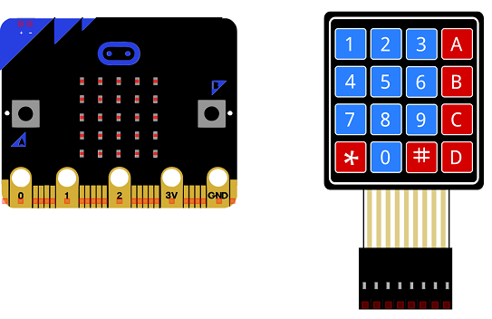
In this tutorial we will see how a key of the 4×4 matrix keypad is pressed, the associated character is displayed in the display of the Micro:bit card.
Necessary components
Micro:bit card
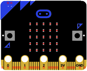
The Micro:bit is a small microcontroller board developed by the BBC in collaboration with a number of partners. It is intended to be used as an educational tool to help teach children and young people how to code and create their own interactive projects. The Micro:bit board is based on a 32-bit ARM Cortex-M0 processor, it has a 5×5 LED matrix display, 2 programmable buttons, on-board accelerometer, compass, Bluetooth Low Energy (BLE) and USB connectivity, and a number of input and output pins.
The Micro:bit board is programmed using a variety of programming languages, including a block-based visual programming language called MakeCode, as well as text-based languages such as Python and JavaScript. It has a large online community and resources to support users, with a range of tutorials, sample codes, and projects available.
The Micro:bit board is designed to be small, lightweight and power-efficient, making it ideal for portable projects, such as wearable electronics, drones and robots. The board can be powered by an external battery, and can be powered by USB.
It’s easy to program and use, it has a number of pre-built libraries and APIs to make it easier to interact with the built-in sensors and output devices, such as the LED matrix and buttons, as well as external sensors and devices.
The Micro:bit is a great tool for introducing children and young people to the world of programming and electronics, it provides a great platform for learning and experimentation, and can be used to create a wide range of interactive projects.
4×4 matrix keypad
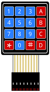
A 4×4 matrix keypad is a type of input device that consists of 16 buttons arranged in a 4×4 grid. These buttons can be used to input numerical or alphanumeric data, and are commonly used in applications such as access control systems, security systems, and point-of-sale terminals. The 4×4 matrix keypad is typically composed of 16 individual switch buttons, arranged in a 4×4 grid. Each button is connected to a row and a column. Pressing a button causes a connection to be made between the row and column to which the button is connected.
There are different ways to connect a 4×4 matrix keypad to a microcontroller like using digital input, or matrix scanning but both methods require some programming and additional components like resistors to protect the microcontroller from high voltage.
When using a 4×4 matrix keypad with a microcontroller, it’s important to consider the pinout and layout of the keypad. Some keypads have the rows and columns labeled, while others may not. In addition, different keypads may have different pinout arrangements, so it is important to consult the datasheet for the specific keypad you are using.
In order to use the keypad, you’ll need to create a keymap that defines the mapping of the keys to their corresponding characters, numbers or codes. Some keypad library already provide a pre-defined keymap of a 4×4 matrix keypad.
Micro:bit GPIO Expansion Board
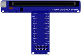
A Micro:bit GPIO (General Purpose Input/Output) expansion board is an add-on board that provides additional input and output pins for the Micro:bit. This allows users to connect additional sensors, actuators, and other devices to the Micro:bit, providing more options for creating interactive projects.
A typical Micro:bit GPIO expansion board will have a number of additional input and output pins that are connected to the Micro:bit’s existing input and output pins. These additional pins may include digital input and output pins, analog input pins, and serial communication pins (such as I2C and UART).
connecting wires

Wires are used to transmit electrical signals and power to various components such as motors, sensors, and microcontrollers. It’s important to properly route and secure the wires to prevent tangles and damage. There are several methods for doing this, including using cable ties, clamps, and wire looms. It’s also a good idea to use different colors or labeling to identify the different wires and their functions. When connecting wires in a robot, it’s important to follow proper safety procedures, such as using the correct wire stripper and connectors, and wearing protective equipment such as gloves and safety glasses.
test plate
A test plate is a type of device used in robotics to test the functionality and performance of various components or systems. It is typically a physical platform or structure that is designed to hold and support various test items or devices, such as sensors, actuators, motors, or other types of mechanical or electrical components. Test plates can be used to simulate different environments or conditions, such as temperature, humidity, vibration, or other factors, in order to evaluate the performance of the components or systems being tested. They can also be used to perform a variety of diagnostic or diagnostic tests, such as stress testing, endurance testing, or other types of evaluations.
Assembly
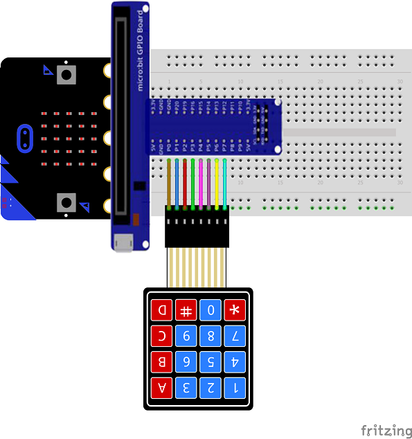
To carry out the assembly, we connect the 8 outputs of the keypad to the 8 pins of the Micro: bit (from P0 to P7)
Makecode program
Here is the Makecode program that allows you to manipulate the 4×4 matrix keypzd with Micro:bit card.


