View location data sent by the NEO-M6 GPS module using the Arduino board

What is GPS?
GPS stands for « Global Positioning System, » which is a network of satellites orbiting the Earth that provide location and time information to GPS receivers on the ground or in other devices, such as smartphones and navigation systems. The GPS system was developed and is operated by the United States government.
GPS receivers use signals from multiple GPS satellites to determine the user’s location and calculate their velocity and time. This information can be used for navigation, tracking, and various other applications.
The GPS system has become an integral part of modern society, with applications in industries such as aviation, shipping, and emergency services, as well as in personal navigation, fitness tracking, and location-based services.
GPS and Arduino are two technologies that can be used together in various applications. An Arduino is a popular open-source hardware platform that allows users to create their own electronic devices and projects. It can be programmed to interface with a GPS module, which allows the device to receive GPS signals and process location data.
One example of an Arduino and GPS project is a GPS tracker. This device can be used to track the location of a vehicle or asset, such as a bicycle or backpack, using GPS signals. The GPS module connected to the Arduino can receive location data and the Arduino can process this data and transmit it to a central server for storage and analysis. The device can also be programmed to send location updates to a smartphone or other device via Bluetooth or Wi-Fi.
Another example of an Arduino and GPS project is a navigation system. An Arduino can be used to control a small screen or display and receive location data from a GPS module. The Arduino can then display the user’s location on a map and provide directions to a destination using real-time GPS data.
There are many other applications for GPS and Arduino, and the possibilities are limited only by the creativity and ingenuity of the user. With the ability to customize and program an Arduino to work with GPS, it is possible to create a wide range of innovative projects and devices.
Purpose of this tutorial
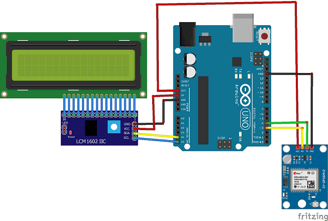
To view location data sent by the NEO-M6 GPS module using Arduino and an LCD I2C 16×2 display, you will need to connect the GPS module and the LCD display to the Arduino and program the Arduino to read and display the location data on the LCD display. Here are the steps to do so:
- Connect the NEO-M6 GPS module and the LCD display to the Arduino using the following connections:
- NEO-M6 VCC to Arduino 5V
- NEO-M6 GND to Arduino GND
- NEO-M6 TX to Arduino pin 4
- NEO-M6 RX to Arduino pin 3
- Connect the LCD display to the Arduino using the following connections:
- LCD I2C SDA to Arduino A4
- LCD I2C SCL to Arduino A5
- LCD I2C VCC to Arduino 5V
- LCD I2C GND to Arduino GND
- Install the LiquidCrystal_I2C and TinyGPS++ library in the Arduino IDE
- Open the Arduino IDE and create a new sketch.
- Add the following code to the sketch to initialize the GPS module, LCD display, and read the location data:
|
1 2 3 4 5 6 7 8 9 10 11 12 13 14 15 16 17 18 19 20 21 22 23 24 25 26 27 28 29 30 31 32 33 34 35 36 37 38 39 40 41 42 43 44 |
#include <TinyGPS++.h> #include <SoftwareSerial.h> #include <LiquidCrystal_I2C.h> // En cas de non fonctionnement, mettez la ligne 8 en // commentaire et retirez le commentaire à la ligne 9. LiquidCrystal_I2C lcd(0x27, 20, 4); // ligne 8 //LiquidCrystal_I2C lcd(0x3F,20,4); // ligne 9 static const int RXPin = 4, TXPin = 3; static const uint32_t GPSBaud = 9600; // The TinyGPS++ object TinyGPSPlus gps; // The serial connection to the GPS device SoftwareSerial ss(RXPin, TXPin); void setup(){ lcd.init(); Serial.begin(9600); ss.begin(GPSBaud); } void loop(){ lcd.backlight(); //lcd.clear(); // This sketch displays information every time a new sentence is correctly encoded. while (ss.available() > 0){ gps.encode(ss.read()); if (gps.location.isUpdated()){ Serial.print("Latitude= "); Serial.print(gps.location.lat(), 6); Serial.print(" Longitude= "); Serial.println(gps.location.lng(), 6); lcd.setCursor(0, 0); lcd.print("Latitude="); lcd.print(gps.location.lat()); lcd.setCursor(0, 1); lcd.print("Longitude="); lcd.print(gps.location.lng()); } } } |
- Upload the sketch to the Arduino.
- Power on the NEO-M6 GPS module and wait for it to acquire a GPS fix (indicated by a flashing LED).
- You should now see location data being displayed on the LCD display, including latitude, longitude, altitude, and other information.
The necessary components
Arduino UNO

The Arduino UNO is a popular microcontroller board designed for hobbyists, educators, and professionals interested in electronics and programming. It is part of the Arduino ecosystem, which includes various boards, shields, sensors, and libraries that can be used to build electronic projects.
The Arduino UNO is based on the ATmega328P microcontroller from Atmel and has 14 digital input/output pins, 6 analog inputs, a 16 MHz quartz crystal, a USB connection, a power jack, and an ICSP header. It can be powered through the USB connection or an external power supply.
The digital pins can be used for input or output, and can also be used for PWM (Pulse Width Modulation) output. The analog inputs can be used to read voltage levels between 0 and 5 volts, and can be used to interface with various sensors and devices.
Programming for the Arduino UNO is done using the Arduino IDE (Integrated Development Environment), which is a software tool that simplifies the process of writing and uploading code to the board. The code is written in C++ and is uploaded to the board using a USB cable.
Overall, the Arduino UNO is a versatile and accessible platform for building electronic projects, and has been used for a wide range of applications, including robotics, home automation, and scientific experiments.
NEO-M6 GPS

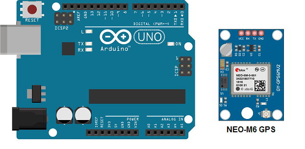
The NEO-M6 GPS (Global Positioning System) module is a small and low-cost GPS receiver module developed by u-blox, a Swiss company that specializes in positioning and wireless communication technologies.
The NEO-M6 GPS module is based on the u-blox M6 GPS chip, which supports multiple satellite positioning systems, including GPS, GLONASS, and Galileo. It also features an integrated high-gain ceramic patch antenna and a low-noise amplifier, which helps to improve the signal reception and accuracy.
The NEO-M6 GPS module supports various data communication protocols, including NMEA (National Marine Electronics Association) and u-blox binary protocol, and can provide position, velocity, and time (PVT) information to the host system with high accuracy and reliability.
The NEO-M6 GPS module can be easily integrated into a wide range of applications, such as drones, smart agriculture, vehicle tracking, and outdoor recreation. It is also available in different form factors, including surface-mount and module versions, to suit different requirements.
In addition, u-blox provides software tools and resources, such as u-center, a powerful GPS evaluation software, and libraries for different programming languages, to help developers quickly and easily integrate the NEO-M6 GPS module into their applications.
Afficheur LCD I2C 16×2
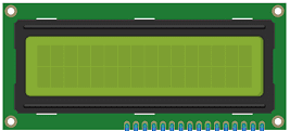
An LCD I2C 16×2 is a type of display module that consists of a 16×2 character LCD (Liquid Crystal Display) and an I2C interface. It is often used in embedded systems and microcontroller projects, where it provides a simple and easy-to-use way to display information to users.
The 16×2 refers to the number of characters the display can show in two rows, with each row containing up to 16 characters. The LCD technology allows for a clear and easy-to-read display of text and simple graphics, making it ideal for displaying data such as sensor readings, system status, and user prompts.
The I2C interface is a serial communication protocol that allows for easy communication between the LCD display module and a microcontroller or other embedded system. The I2C protocol requires only two wires, making it simple to connect and use in a project.
The LCD I2C 16×2 module typically includes an integrated I2C interface controller, which simplifies the task of driving the display. This controller can handle all the necessary signal conversion and timing for the LCD module, allowing the host system to communicate with the display using simple I2C commands.
Using an LCD I2C 16×2 module can be a convenient and efficient way to display information in an embedded system or microcontroller project, without the need for complex graphics libraries or low-level display drivers. It is commonly used in applications such as automation, robotics, and instrumentation, where simple and clear visual feedback is important.
Connecting wires
Connecting wires are electrical wires used to connect various electrical components in a circuit. They are an essential component of any electrical or electronic system, as they are used to transfer electrical energy and signals between the different parts of the circuit.
Test plate
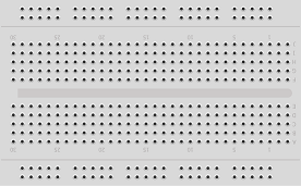
A test plate is a type of device used in robotics to test the functionality and performance of various components or systems. It is typically a physical platform or structure that is designed to hold and support various test items or devices, such as sensors, actuators, motors, or other types of mechanical or electrical components. Test plates can be used to simulate different environments or conditions, such as temperature, humidity, vibration, or other factors, in order to evaluate the performance of the components or systems being tested. They can also be used to perform a variety of diagnostic or diagnostic tests, such as stress testing, endurance testing, or other types of evaluations.
Assembly
