App Inventor Arduino HX711 Project
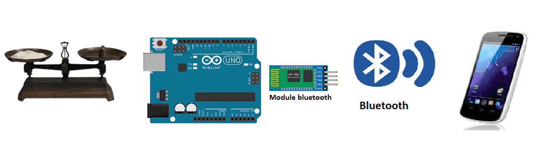
Weighing scale using HX711 and Arduino for remote weight monitoring (by bluetooth)
A weighing scale is a device that is used to measure the weight of an object or a group of objects. There are many different types of weighing scales, including mechanical scales, electronic scales, and digital scales.
Mechanical scales use a spring or balance beam to measure weight. They are typically less accurate than electronic or digital scales, and are often used for rough estimates of weight.
Electronic scales use a load cell to convert weight into an electrical signal. They are typically more accurate than mechanical scales, and can be used to measure weight with greater precision.
Digital scales use a load cell to convert weight into an electrical signal, which is then displayed digitally. They are typically the most accurate type of scale and can display weight in a variety of units.
An Arduino can be used to control and read data from a weighing scale by interfacing with the scale’s load cell sensors and utilizing the Arduino‘s analog-to-digital converter (ADC) to convert the sensor’s output into a weight measurement. This can be done by connecting the load cell sensors to an amplifier circuit, which amplifies the small electrical signals produced by the sensors and sends them to the Arduino. The Arduino can then read the amplified signals using its ADC and convert them into weight measurements, which can be displayed or used to control other devices.
Purpose of project:
A weighing scale with Bluetooth and Arduino allows you to wirelessly connect your scale to other devices, such as a smartphone or computer, and receive weight measurements in real-time. This can be achieved by using a load cell sensor to measure the weight, an HX711 amplifier to amplify the load cell’s output and convert it to a digital signal, and an Arduino microcontroller board to control the HX711 and handle the Bluetooth communication.
To implement a Bluetooth connection, you can use a Bluetooth module such as the HC-05 or HC-06, which can be connected to the Arduino‘s serial communication pins. Once connected, the Arduino can send and receive data to and from the Bluetooth module, allowing you to wirelessly connect to the scale and receive weight measurements.
The Arduino would read data from the HX711 and the weight can be converted to a digital signal, which can be sent over the Bluetooth connection to a smartphone or computer. On the other end, a mobile application or software can be used to display the weight measurements and to store the data.
It’s important to note that in order to implement a weigh scale with Bluetooth you will need to have some knowledge of programming in C++ and experience with the Arduino platform as well as a good understanding of the load cells and the HX711. Also, it’s important to note that the code and the library you need to use will depend on the type of load cells and the Bluetooth module that you have.
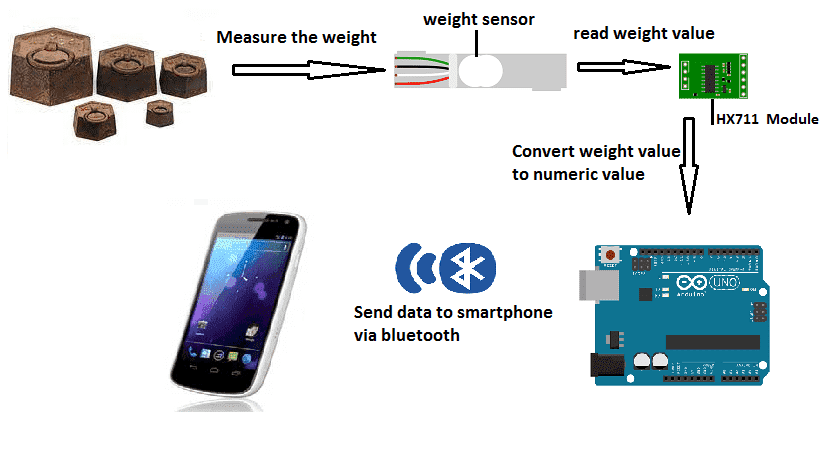
In this project, we will build a weighing scale equipped with the Arduino board, the HX711 module and weight sensor for remote weight monitoring by a smartphone via Bluetooth.
This is why we will create two programs: a mobile application with App Inventor for the smartphone and a program for the Arduino board.
Necessary components
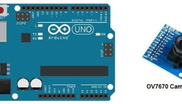
Arduino UNO
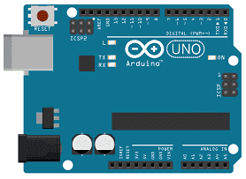
The Arduino UNO is a popular microcontroller board based on the ATmega328P microcontroller. It has 14 digital input/output pins (of which 6 can be used as PWM outputs), 6 analog inputs, a 16 MHz quartz crystal, a USB connection, a power jack, an ICSP header and a reset button. It can be programmed using the Arduino software (IDE) which is available for Windows, macOS and Linux.
The Arduino UNO has a number of facilities for communicating with a computer, another Arduino or other microcontrollers. The microcontroller on the board is programmed using the Arduino programming language and the Arduino development environment (IDE).
HX711 module

The HX711 is an integrated circuit that is commonly used to interface with load cells, which are sensors used to measure weight. The HX711 is a 24-bit analog-to-digital converter (ADC) designed specifically for weigh scales and other industrial control applications. It has two input channels for differential measurements and can convert the analog signals from the load cells into a digital representation of the weight being measured.
The HX711 can be easily interfaced with an Arduino microcontroller through its digital interface. The HX711 has three pins: VCC, GND, and DT. The VCC and GND pins are used to power the chip and the DT pin is used to send and receive data to and from the Arduino. The HX711 communicates with the Arduino using a serial protocol, so it can be easily integrated with any load cell.
The HX711 is a very popular choice for load cell amplifiers because it is inexpensive, easy to use, and has a high resolution and accuracy. It also has a low noise level, making it ideal for use in low-light environments.
weight sensor
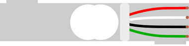
A weight sensor, also known as a load cell, is a type of transducer that converts a force, such as weight, into an electrical signal. Load cells are commonly used in industrial and commercial applications to measure the weight of objects, such as in scales and weighing systems. There are several types of load cells available, each with their own unique characteristics and advantages.
The most common types of load cells are:
- Strain gauge load cells: These load cells use a strain gauge, which is a thin film resistor, to measure changes in resistance caused by the application of a force. They are the most common type of load cell and are used in a wide variety of applications.
- Compression load cells: These load cells are designed to measure force in a compression mode. They typically have a cylindrical shape and are used in applications such as industrial weighing, force testing, and material testing.
- Tension load cells: These load cells are designed to measure force in a tension mode. They are typically used in applications such as hopper and tank weighing, force testing and material testing.
- Beam load cells: These load cells are designed to measure force by bending a beam. They are typically used in platform scales, conveyor belt scales, and other industrial weighing systems.
Each type of load cell has its own set of characteristics and specifications, such as capacity, accuracy, and size, which need to be considered when selecting a load cell for a specific application.
In addition, it’s important to note that load cells are not the only type of weight sensors, there are other types such as pressure sensors and force-sensitive resistor.
HC-06 module
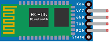
The HC-06 is a Bluetooth module that can be used to add wireless communication capabilities to devices such as the Arduino microcontroller. It is a slave module, which means that it can only connect to other devices as a slave and cannot initiate a connection.
The HC-06 is easy to interface with an Arduino board. It has 6 pins: VCC, GND, TXD, RXD, State, and EN. The VCC and GND pins are used to power the module, the TXD and RXD pins are used to send and receive data to and from the Arduino, the State pin is used to indicate the status of the module, and the EN pin is used to enable or disable the module.
The HC-06 is configured by default as a slave device with a baud rate of 9600 bps, 8-N-1 and the default name of « HC-06« . The baud rate, name, and other parameters can be configured by using AT commands.
The HC-06 can communicate with other Bluetooth devices such as smartphones and tablets, and can be used to send and receive data wirelessly. This makes it an ideal choice for a variety of applications such as remote control, wireless monitoring, and data logging.
Connecting wires

Wires in a robotic system are used to connect and transmit electrical signals between different components of the robot. These components can include sensors, actuators, motors, and the microcontroller, such as an Arduino. The wires in a robotic system are typically made of copper and are insulated to prevent electrical interference and short circuits.
The type of wires used in a robotic system depends on the specific application and requirements of the robot. For example, a robot that requires high-current power transmission may use thicker, high-gauge wires, while a robot that requires a high degree of flexibility and movement may use thinner, more flexible wires.
Assmbly:
-
We connect the VCC pin of the hx711 module to the 3.3V pin of the Arduino
-
We connect the GND pin of the hx711 module to the GND pin of the Arduino
-
We connect the DT pin of the hx711 module to pin 3 of the Arduino
-
We connect the SCK pin of the hx711 module to pin 2 of the Arduino
-
We connect the E+ pin of the hx711 module to the red wire of the weight sensor
-
We connect the E- pin of the hx711 module to the black wire of the weight sensor
-
We connect pin A- of the hx711 module to the white wire of the weight sensor
-
We connect the A+ pin of the hx711 module to the green wire of the weight sensor

Scale operation
Arduino program
Here is the program needed to connect the Arduino board to the smartphone and send the value of the weight measured by the HX711 module to the smartphone.
|
1 2 3 4 5 6 7 8 9 10 11 12 13 14 15 16 17 18 19 20 21 22 23 24 25 26 27 28 29 30 31 32 33 34 35 36 37 38 39 40 41 42 43 44 45 46 47 48 49 |
#include <SoftwareSerial.h> #include "HX711.h" #define LOADCELL_DOUT_PIN 3 #define LOADCELL_SCK_PIN 2 HX711 scale; SoftwareSerial hc06(4,5); float calibration_factor = 235; //-7050 this variable to be adjusted according to ths weight sensor void setup() { hc06.begin(9600); Serial.begin(9600); Serial.println("HX711 calibration sketch"); Serial.println("Remove all weight from scale"); Serial.println("After readings begin, place known weight on scale"); Serial.println("Press + or a to increase calibration factor"); Serial.println("Press - or z to decrease calibration factor"); scale.begin(LOADCELL_DOUT_PIN, LOADCELL_SCK_PIN); scale.set_scale(); scale.tare(); //Reset the scale to 0 long zero_factor = scale.read_average(); //Get a baseline reading Serial.print("Zero factor: "); //This can be used to remove the need to tare the scale. Useful in permanent scale projects. Serial.println(zero_factor); } void loop() { scale.set_scale(calibration_factor); //Adjust to this calibration factor Serial.print("Reading: "); Serial.print(scale.get_units(), 1); hc06.print(scale.get_units(),1); // Sending the weight value to smartphone Serial.print(" lbs"); //Change this to kg and re-adjust the calibration factor if you follow SI units like a sane person Serial.print(" calibration_factor: "); Serial.print(calibration_factor); Serial.println(); if(Serial.available()) { char temp = Serial.read(); if(temp == '+' || temp == 'a') calibration_factor += 10; else if(temp == '-' || temp == 'z') calibration_factor -= 10; } delay(1000); } |
Creating the application with App Inventor:
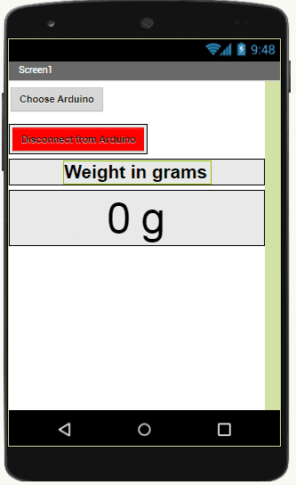
We will create a mobile application named ‘ArduinoPoids’ with App Inventor which allows to receive the weight measured by the Arduino board.
We therefore suggest that you create the design of the application, with the following visual:
Programming with App Inventor
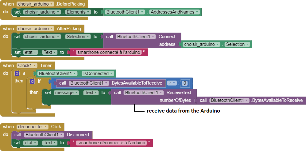
To program the application, App Inventor offers us to use the Blocks space which allows you to create a program in the form of a block diagram. Very easy to use but requires some programming logic.
Here is the program of the application made in the Blocks space of the App Inventor:
You can also see

0 commentaire
Leave a comment


Recent tutorials


Most viewed tutorials


Most commented tutorials


Scroll to Top